
Flex & Rigid-Flex PCB Capabilities
FLJ PCB supports flexible and rigid-flex constructions for compact interconnects and integrated electronics. Separate process tables help you compare the two board types.
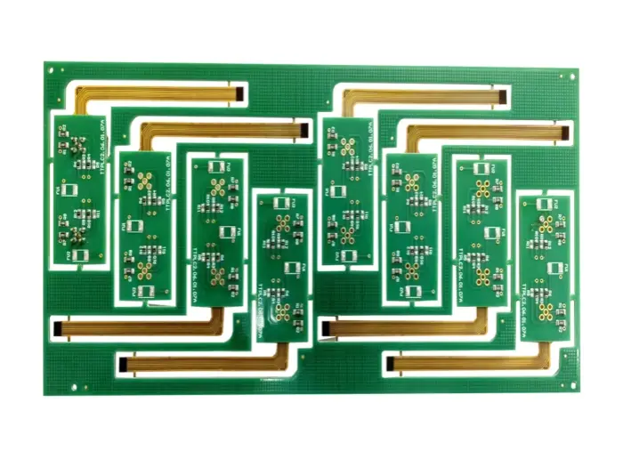
Choose construction around the mechanical task
Flexible PCBs use a flexible base. Rigid-flex boards connect rigid circuit areas through integrated flexible sections.
Flex provides a compact interconnect or accommodates defined movement. Rigid-flex brings several board areas into one construction and reduces separate connectors. The choice follows assembly space, connection needs, bend locations and whether movement happens only during installation or throughout product life.
Layer count alone does not define flexibility. Copper distribution, flex thickness, adhesive, coverlay, stiffeners and bend geometry contribute to mechanical behavior. Describe how the circuit will be installed and used so review reflects the actual product.
Flexible PCB process capabilities
Published process ranges are matched to your material and construction during engineering review.
Material, copper and layer structure determine which features are practical together. The smallest values are not an instruction to use every minimum in one design.
| Merkmal | Published FPC capability |
|---|---|
| Maximum layers | 16 |
| Minimum finished thickness | 0.04 mm |
| Maximum size | 500 × 2200 mm |
| Minimum laser hole | 0,025 mm |
| Minimum mechanical hole | 0,1 mm |
| Minimum line / space | 0.035 / 0.035 mm |
| Minimum coverlay bridge | 0,1 mm |
| Minimum coverlay opening | 0.30 × 0.30 mm |
| Single-ended impedance tolerance | ±7% |
| Base materials | Polyimid, LCP, PET |
| Stiffeners | FR4, PI, PET, steel, aluminum, PSA and nylon |
Rigid-flex PCB process capabilities
Rigid and flexible areas share one construction, with different mechanical roles.
Rigid-section and flex-section thickness serve different purposes. A stack-up drawing identifies transitions, flex layers, coverlay and reinforcement so the board can be fabricated and assembled as intended.
| Merkmal | Published rigid-flex capability |
|---|---|
| Maximum layers | 30 |
| Maximum finished thickness | 4.0 mm |
| Maximum production size | 500 × 1000 mm |
| Minimum laser hole | 0.075 mm |
| Maximum aspect ratio | 13:1 |
| Inner line / space | 0.04 / 0.04 mm |
| Outer line / space | 0.05 / 0.05 mm |
| Solder-mask registration tolerance | 0.035 mm |
| Single-ended impedance tolerance | ±7% |
| HDI combination | 3+N+3 listed for prototype work |
Coverlay, stiffeners and finish selection
Coverlay protects flexible conductors while openings expose pads and connection areas.
Stiffeners provide local connector support or assist assembly handling. Their position and thickness affect final fit, especially at mating areas. Drawings can show reinforcement, adhesive locations and finished dimensions without every detail being settled before the first inquiry.
Published finishes include ENIG, ENEPIG, OSP, electroplated gold, immersion silver, immersion tin and combinations. Selection follows soldering, contact wear and storage. Connector contacts and solderable pads may have different needs.
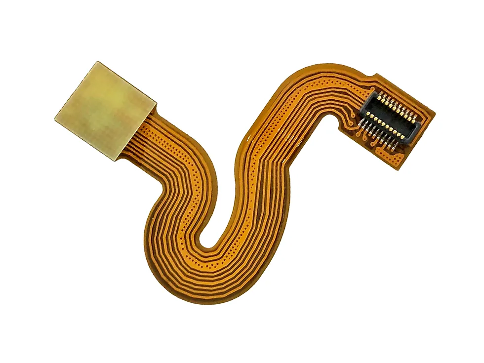
Bend regions, stiffeners and finished fit
Flex designs often have several local thicknesses and mechanical tasks. We help connect those regions with fabrication and assembly.
| Design area | Useful information | How we help |
|---|---|---|
| Bend region | Static fold or repeated movement; radius and orientation | Share the mechanical drawing or motion description |
| Connector thickness | Finished thickness in the insertion region | Match the connector drawing and local stiffener |
| Coverlay and stiffener | Opening, overlap, adhesive and reinforced region | Review the local layer construction |
| Copper and bend duty | Copper structure, routing and target use | Discuss geometry and any bend verification needed |
| Acceptance | Regional dimensions, electrical checks and relevant records | Agree the checks that support assembly and product fit |
Construction review and assembly support
Send existing board data, stack-up or outline and tell us where the circuit bends.
We review transitions, bend regions, openings, drilling and interconnects with your team. For repeatedly moving designs, operating motion and service conditions matter more than a generic bend-radius claim. We help identify the information needed to assess the construction.
Assembly can be coordinated with fabrication. Fixtures or carriers support flexible circuits during placement and soldering. Approved materials, stack-up and mechanical details keep fabrication and assembly instructions aligned on repeat builds.
Frequently asked questions
Is rigid-flex the same as flex with a stiffener?
No. A stiffener provides mechanical support on a flex circuit. Rigid-flex integrates rigid and flexible circuit areas within one board construction.
Can you help before bend geometry is final?
Yes. Send the available layout and describe installation or movement. We can discuss details affecting fabrication.
Does the table establish dynamic bend life?
No. Manufacturing values do not establish a product lifetime. Repeated movement needs construction and qualification matched to the application.
Can assembly be included?
Yes. We review components, support tooling and soldering with the board construction.
Explore related capabilities
Let’s review your next build
Send your available board files, drawings or project questions. Our team will review the information and follow up with you about the next step.