
Hjem / PCB Stencils
PCB Stencils
Laser-cut stainless-steel stencils for prototype and production SMT assembly, supplied as framed components or separate foils.
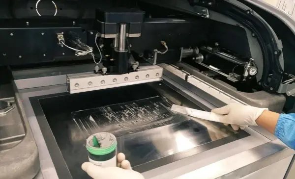
FLJ makes the aperture pattern, foil construction and mounting format fit the board and its printing setup. Order a stencil on its own or include it with your PCB and assembly build.
Framed or frameless · Uniform or local-step thickness · Electropolishing and surface-treatment options
Stencil Formats for Your Printing Setup
A stencil carries the solder-paste openings for a particular board or production panel. Its mounting format determines how the steel foil is held over that pattern during printing.
Framed Stencils
The steel foil is permanently tensioned within a frame, with a mesh border supporting the foil. The assembled frame provides a tool that can be clamped into a compatible printer for repeated use.
Match the frame to the machine’s mounting arrangement, then check that the entire paste image fits within the working region.
- Supplied as
- Cut foil mounted and tensioned in its frame
- Match to
- Printer clamps, frame envelope and required image area
Frameless Foils
A frameless stencil is supplied without a permanent frame. It can serve a manual printing fixture or a compatible reusable tensioning system; the intended holder determines how the sheet is secured.
Foil dimensions, mounting features and the position of the cut image must suit that arrangement. The foil needs stable support and registration to the board throughout the print.
- Supplied as
- A separate foil with the required aperture pattern
- Match to
- Holder or tensioning system, sheet outline and image position
Foil Thickness, Apertures and Paste Release
Small terminals and larger solder areas place different demands on the same stencil. Thickness and aperture geometry are selected together, with the paste and printing process in view.
Balancing Paste Volume and Release
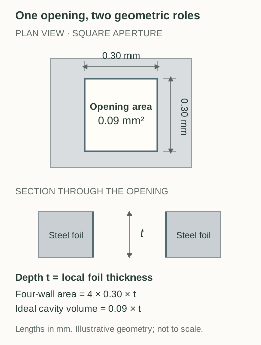
An aperture has a footprint in the foil and a depth through it. For an ideal straight-walled opening, the footprint area multiplied by the local foil thickness gives the cavity volume available to hold paste.
Increasing thickness increases the cavity volume, but also increases the wall area in contact with the paste. Reducing thickness has the opposite effect. The area ratio describes this geometric relationship; it helps explain why a small opening in a thick foil can be more demanding to release cleanly.
The deposited paste also depends on aperture filling, wall condition, paste properties and separation from the board. The ideal cavity volume is a design reference, rather than a measurement of the printed deposit.
One Opening, Two Foil Thicknesses
For the same 0.30 × 0.30 mm square opening, the footprint area is 0.09 mm² and the perimeter is 1.20 mm. Changing only the foil thickness gives:
Scroll to compare the thickness, volume and area ratio →
| Local foil thickness | Ideal cavity volume | Opening / wall area ratio |
|---|---|---|
| 0.12 mm / 120 µm | 0.0108 mm³ | 0.625 (0.09 ÷ 0.144) |
| 0.10 mm / 100 µm | 0.0090 mm³ | 0.750 (0.09 ÷ 0.120) |
Calculated straight-walled geometry. The thinner foil holds less paste in the ideal cavity and has a higher opening-to-wall area ratio. These values illustrate the tradeoff; they are not measured deposits or acceptance limits.

Step Stencils for Mixed Paste Requirements
A uniform foil can leave a compromise between the needs of fine openings and joints requiring more paste. A step stencil introduces locally thinner or thicker regions, so different parts of the image can use different aperture depths.
The position and extent of a step must fit the print regions and squeegee travel. Step depth, surrounding clearance and the aperture pattern are considered as one construction.
A large thermal-pad opening can also be divided into smaller windows. That changes the opening footprint rather than the foil thickness. Component recommendations and soldering needs guide the pattern. Our PCB assembly design review connects those choices with the selected package and board land pattern.
Laser-Cut Stencil Manufacturing
FLJ manufactures the stencil from the released paste pattern, with the selected foil construction and mounting format carried through cutting, surface treatment and final tool preparation.
Aperture Cutting and Wall Finishing
Laser cutting forms the specified openings in the steel foil. Their positions and shapes follow the selected board or panel image, including any regional aperture changes required for the assembly.
Post-cut cleaning removes processing residue. Electropolishing smooths the cut aperture walls; optional release-oriented coatings modify the surface that contacts the paste. These treatments address surface condition while the opening footprint and foil depth remain central to the print design.
The cut pattern defines deposit locations, local thickness sets the opening depth, and the finished walls influence transfer from the tool.
Mounting, Identification and Inspection
Framed stencils include mounting and tensioning the foil. The completed tool is checked for aperture pattern, relevant dimensions, surface condition and its mounted or sheet configuration. Identification connects the stencil to the board revision, foil thickness and intended printing side.
Cleanliness, flatness and stable mounting matter at the printing interface. The delivered frame or separate foil must retain the intended relationship between the aperture image and the board.

The completed stencil is secured in its intended printer or holder and aligned with the board. The squeegee fills the apertures; separation of the foil and board leaves the paste on the pads. The mounting, image position and supported board surface work together at this interface.
Stencil inspection checks the steel tool. During SMT printing and solder-paste inspection, the deposited paste is checked on the board before placement. The tool’s aperture dimensions and the measured print result describe different parts of the process.
Stencil Dimensions, Alignment and Artwork
Frame Size and Printable Area
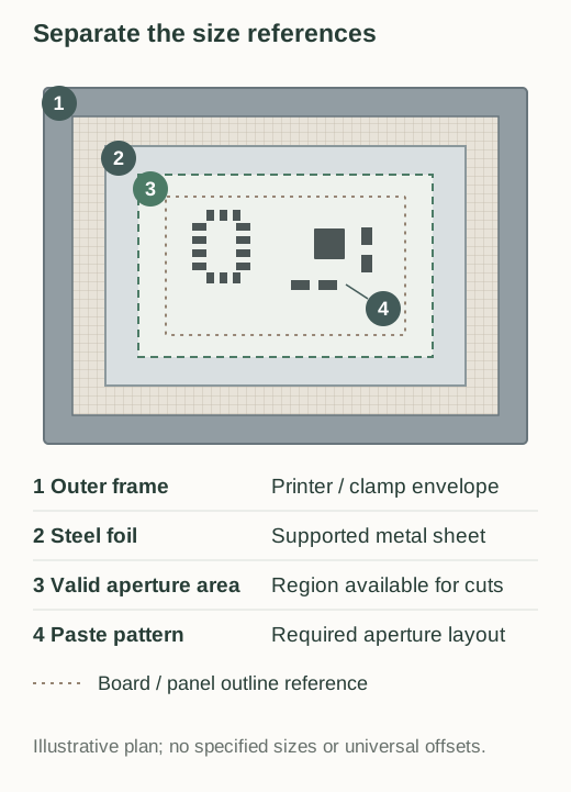
The outer frame determines the tool’s machine envelope. Inside it, the foil and support arrangement leave a working region for the apertures. The complete board or panel paste image must fit within that region.
A frame’s outside dimension alone does not establish the printable board size. Foil extent, mounting and usable image area need to be matched as one compatible combination.
The printing setup also needs room for the squeegee stroke and its start and finish positions. That travel extends beyond the aperture pattern and must suit the printer and mounted foil; it is a separate check from keeping the cut image inside the valid aperture region.
- Outer frame
- Match the printer’s available space and clamping arrangement.
- Steel foil
- Match the retained sheet and its support or tensioning features.
- Aperture region
- Keep every required opening inside the region available for aperture production.
- Board / panel image
- Keep the intended pattern, position and orientation within the working region.
Top and Bottom Paste Data
The paste layers define the intended stencil openings. They differ from the solder-mask layers, which define exposed areas of the board surface. Include the relevant paste-layer files or stencil drawing with the board or panel revision.
Top and bottom images can require different patterns and orientations. If both are arranged on one foil, the combined image must suit its usable region and the intended printing setup.
Fiducials support alignment. Their form and position need to match the printer or fixture and be identified with the intended board-facing and squeegee-facing sides.
Get a Stencil Made for Your Build
Send the paste data, board or panel dimensions, and printer or mounting requirements. FLJ supplies the finished stencil separately or with coordinated PCB and SMT assembly.