
















Resistors: Principles, Types, and Color Code Guide
The main function of a resistor is to limit current, and by doing this control the circuit, direct current to a certain component, or protect another component, and so on. As usual, we will first introduce the principle and function of resistors:
1. Understanding Resistors and Circuit Symbols
The resistor is one of the most basic electronic components. Its function is to obstruct current and cause a voltage drop. Usually, a resistor has two leads connected to the two ends or sides of the resistor body. The resistor body is usually made of material with relatively low conductivity. The unit of resistance is the ohm, shown by the Greek letter Ω.
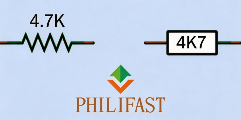
In circuit diagrams, the resistor symbol is shown as in the figure above (left: traditional circuit symbol; right: recent European-style symbol). In European circuit diagrams, the American-style symbol sometimes appears, and vice versa. The letters K and M stand for kilohms (thousand ohms) or megohms (million ohms). These letter codes are more often used in Europe, but they also appear in the US. Sometimes, the letter can take the place of a decimal point. For example, a 4.7K resistor can be written as 4k7, and a 3.3M resistor can be written as 3M3, and so on.
2. Main Uses of Resistors
Resistors are often used to limit the charging rate of capacitors, to provide proper control voltage for semiconductors (such as bipolar transistors), to protect LEDs or other semiconductor parts from too much current, to adjust or limit the feedback frequency in audio circuits (together with other parts), to pull the voltage of an input pin up or down in digital logic circuits, or to control the voltage value at a certain point in a circuit. In this last use, two resistors can be placed in series as a voltage divider. If a different resistance is needed, a potentiometer can also be used as a resistor.
3. Appearance, Power Rating, and Tolerance
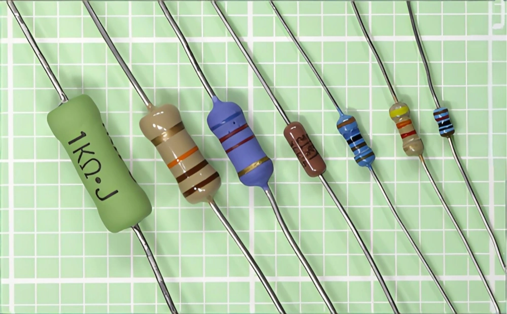
Figure 2 shows resistors of different power ratings. From left to right, the power dissipation ratings are 3 watts, 1 watt, 0.5 watt, 0.25 watt, 0.25 watt, 0.25 watt, 0.125 watt. The tolerances From left to right are ±5%, 5%, 5%, 1%, 1%, 5%, and 1%. A beige resistor body means a tolerance of 5%, while a blue body usually means a tolerance of 1% or 2%. Also, blue and dark brown resistors contain metal oxide film parts, while beige and green resistors contain carbon film. If the resistor body is blue or brown, it means it contains metal oxide film. If the resistor body is beige or green, it means it contains carbon film.
4. Principle and Calculation Formulas
Principle
In the process of obstructing current and dropping voltage, the resistor absorbs electrical energy and then releases it as heat. In most modern circuits, the heat dissipated is below one watt.
If R stands for resistance (in ohms), I stands for the current flowing through the resistor (in amperes), and V stands for the potential difference (voltage drop) across the resistor, then according to Ohm’s law, the relationship is:
In other words, a one-ohm resistor means that a potential difference of one volt allows a current of one ampere to pass.
If W stands for the electrical power dissipated by the resistor (in watts), then in a DC circuit:
By rearranging Ohm’s law, we can express wattage using current and resistance:
Of course, we can also express wattage using voltage and resistance:
These formula substitutions can be used to find values when you do not know the voltage or current.
In AC circuits, the relationship among these variables is similar, only the power formula is a bit more complex.
5. Types of Resistors
- Axial resistors have a round body with a lead coming out from each end. Radial resistors are less common; they have two parallel leads extending from one end of the body.
- Precision resistors are usually defined as having a tolerance of less than ±1%.
- General resistors have poorer stability and their values are less accurate.
- Power resistors usually dissipate one to two watts or more of electrical energy. They are used especially in power supplies or power amplifiers. Usually, these resistors are larger in size and may need a heat sink or a fan.
- Wire-wound resistors are used where the part needs to withstand heat. Usually, a wire-wound resistor has a heat-resistant tube or a flat/cylindrical body, wound with many layers of protective wire. The wire material is often nichrome (Ni-chrome), covered with a plastic coating. The circuit board temperature must be limited because the heat generated when current passes through the wire may cause problems. But in everyday appliances like hair dryers, toasters, and fan heaters, the nichrome parts are normally used to generate heat. Also, wire-wound resistors are used in 3D printers to melt plastic (or other compounds) and output the product.
- Thick film resistors are sometimes made in a flat square shape. The right picture shows an example; the flat
surface can dissipate 10 watts, and the
resistance value is 1K.
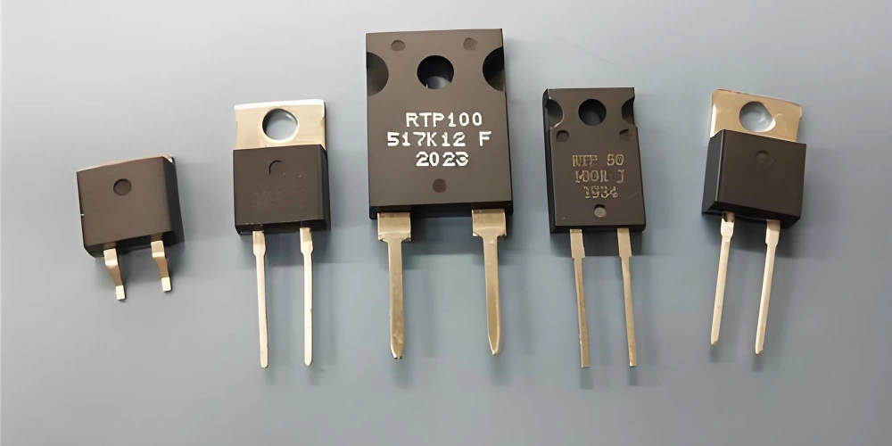
- Surface mount resistors usually contain a layer of resistive ink printed on a body made of alumina and ceramic. The common size is six millimeters, which is the 2512 package. Each surface mount resistor has two nickel-plated terminals with solder coating that melts when connecting to the circuit board. Also, the top surface is usually coated with a black circular epoxy resin to protect the resistor body.
6. Value Coding
6.1 Traditional Color Code System
Traditionally, through-hole axial resistors are marked with three color bands to show the resistance value. The first two bands each stand for a digit from 0 to 9. The third band means the multiplier (the power of ten, or how many zeros to add, from zero to nine). Also, there may be a fourth band, silver or gold, standing for ±10% or ±5% tolerance. But this form is less common now.
Currently, many resistors have five color bands. This makes it easier to show intermediate or fractional values. In this system, the first three bands represent the value (the same digit system as before), the fourth band is the multiplier (the power of ten), and the fifth band at the other end of the resistor shows the tolerance.
In the chart below, the digit or decimal values are shown at the top in a “spectrum” form, and the tolerance (or precision) is shown below with silver, gold, and other colors as ± percent.
| Color | Digit | Multiplier (10x) | Tolerance |
|---|---|---|---|
| Black | 0 | ×100 (×1) | – |
| Brown | 1 | ×101 (×10) | ±1% |
| Red | 2 | ×102 (×100) | ±2% |
| Orange | 3 | ×103 (×1,000) | – |
| Yellow | 4 | ×104 (×10,000) | – |
| Verde | 5 | ×105 (×100,000) | ±0.5% |
| Blue | 6 | ×106 (×1,000,000) | ±0.25% |
| Violet | 7 | ×107 | ±0.1% |
| Grey | 8 | ×108 | ±0.05% |
| Blanco | 9 | ×109 | – |
| Gold | – | ×10-1 (÷10) | ±5% |
| Silver | – | ×10-2 (÷100) | ±10% |
| (None) | – | – | ±20% |
6.2 Color Code Reading Examples and Important Notes
In the figure below, there are two resistor color code examples.
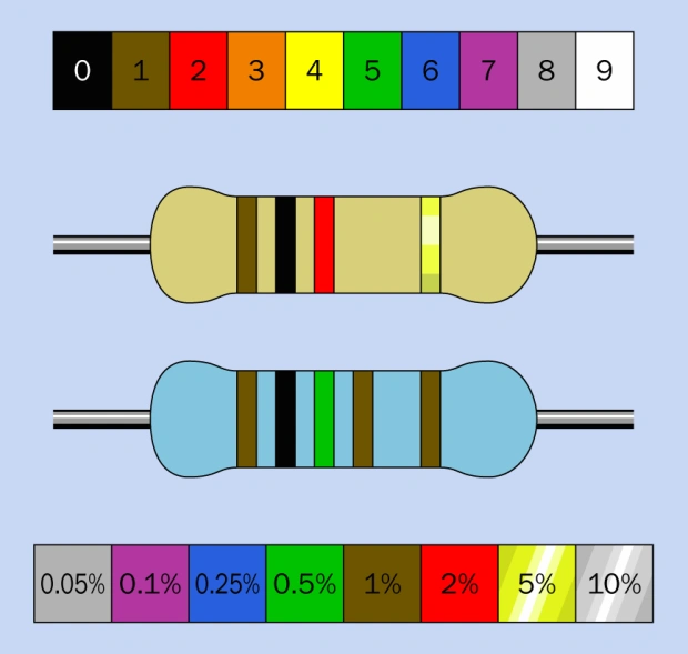
The top resistor value is 1k. From left to right: brown, black (1, 0), then the third band is red (meaning add two zeros). Finally, the gold band means a tolerance of 5%. The bottom resistor value is 1.05k. From left to right: brown, black, green (1, 0, 5), followed by a fourth brown band (meaning add one zero). The black band on the far right means a tolerance of 1%.
A long time ago, resistors were sometimes coded with a body-tip-dot system. In that system, the body color was the first digit, the tip color was the second digit, and the dot meant the number of zeros. The digit spectrum in this system is exactly the same as mentioned before.
In all modern coding systems, the three or four bands that show the value are close together, with a larger gap between them and the tolerance band. When reading the bands, the three or four value bands should be on the left. But it is confusing that some resistors use the first three bands for the value, the fourth band for tolerance, and a fifth band on the other end for precision. But this system is quite rare. Also, in some special uses, other coding systems are used, such as for military equipment.
6.3 Digital Coding for Surface Mount Resistors
Also, some modern resistors have their value printed directly in digits on the body. Surface mount resistors are also marked with digits, but that is a coding system and should not be read directly as the value. The last digit tells how many zeros follow the value, the next two or three digits represent the value itself. The letter R is used to show a decimal point. So, a surface mount resistor marked 3R3 has a value of 3.3 ohms. 330 means 33 ohms. 332 means 3,300 ohms. A surface mount resistor with marking 2152 has a value of 21,500 ohms.
There is a type of surface mount resistor with a zero marking. This means it is a zero-ohm resistor, and its function is actually the same as a jumper. This is done for convenience, so that it can be placed by automated assembly equipment. Its function is very simple: to connect parts on the circuit board.
6.4 Resistance Value Marking Practice in Circuit Diagrams
When the resistance value is printed on circuit diagrams, poor copy quality may cause the decimal point to be lost, or cause stains that can be mistaken for a decimal point. To solve this problem, the European system uses a letter to take the place of the decimal point. So, a 5.6k resistor is printed as 5k6, and a 3.3M resistor is printed as 3M3. But this marking practice is not very common in the US.