
PCB Assembly Capabilities
FLJ PCB supports SMT, through-hole and mixed-technology assembly, with component sourcing, programming and testing coordinated around your board design and production stage.
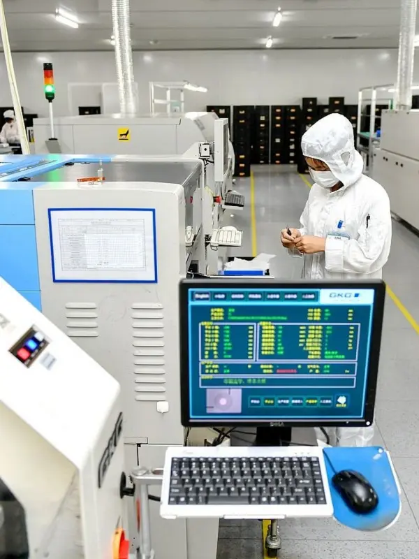
Assembly support from board to tested PCBA
A PCB assembly build combines the bare board, approved components, soldering process and the checks that establish acceptance.
We support prototypes, small runs and volume production. SMT handles surface-mounted parts; through-hole assembly supports connectors and other leaded components; mixed builds combine both. The production route follows the component mix and product requirements rather than a single fixed sequence.
For turnkey work, FLJ PCB coordinates sourcing and fabrication with assembly. Customer-supplied parts and mixed sourcing can also form part of the build. This lets your team retain control of selected items while keeping manufacturing tasks connected.
Production resources and their roles
Our published assembly resources include seven SMT lines, two DIP lines and two manual soldering lines.
These resources describe the production configuration, not a guaranteed package pitch or throughput for every design. Package dimensions, board support, pad geometry and component availability are reviewed together.
| Resource | Build task |
|---|---|
| 7 SMT lines | Surface-mount assembly |
| Yamaha YRM20 | Placement around approved board and component data |
| Automatic printing and 3D SPI | Prepare and inspect paste deposits |
| Povratno taljenje | SMT joints using a matched process |
| 2 DIP lines | Through-hole work |
| 2 manual soldering lines | Product-specific soldering and finishing |
| AOI and X-ray | Visible features and selected hidden joints |
SMT, BGA and through-hole preparation
Fine-pitch and hidden-joint packages need board data and component information that support the placement and inspection route.
BGA packages bring considerations around land patterns, paste deposition, warpage and hidden joints. X-ray supports selected joint review. Through-hole parts need attention to finished hole dimensions, insertion access, solder flow and neighboring components.
Double-sided boards and flex assemblies may need carriers or a planned soldering sequence. Heavy components and connectors can require fixture support. These choices are resolved during process preparation so boards can be handled and inspected consistently.
Component supply, programming and test
Turnkey, consigned and mixed component supply are available project models.
AOI, X-ray, ICT and functional tests answer different questions. Coverage follows the product rather than making every method an automatic step. Firmware and fixture preparation can be planned alongside procurement and fabrication.
| Work area | Project coordination |
|---|---|
| Component sourcing | BOM identity, availability and alternatives for approval |
| Customer parts | Packing, quantities and component identity |
| Programming | Approved firmware and programming method |
| ICT and functional test | Test access, fixtures and acceptance limits |
| Outgoing records | Revision, inspection scope and test results |
Assembly specification review
Start with your board, BOM or application description. Our engineers will help connect the package mix and mechanical details with a practical assembly route.
| Specification | FLJ assembly scope | Project guidance |
|---|---|---|
| Board and panel dimensions | Rigid, flex and rigid-flex assembly routes | Send the outline or proposed panel; we match clamping, support and tooling to the build |
| Board thickness and component height | Reviewed with the soldering route and fixture | Share enclosure constraints or tall parts so handling and clearance can be planned |
| Smallest passive package | Matched to BOM package, pad and stencil data | We check the exact package designation and units with your files |
| Fine-pitch packages | BGA, WLCSP, QFN and POP in FLJ’s published assembly scope | Package pitch, pad design and inspection are reviewed together |
| Placement equipment reference | Yamaha YRM20: published accuracy ±0.025 mm | Equipment statement; actual assembly acceptance follows the board and package specification |
| Through-hole and mixed assembly | DIP, wave and manual-soldering resources | Component mix and board construction guide the sequence |
| Programming and test | Defined for the delivered assembly | Share firmware, interfaces or functional goals; we help develop the build scope |
Component handoff and panel preparation
Customer-supplied parts and existing panels can be discussed before every production detail is final. We will follow up on the information that helps prepare your build.
| Build detail | Starting point | How we help |
|---|---|---|
| Component presentation | Tell us whether parts are in reels, cut tape, trays or tubes | We discuss feeder preparation and any useful additions with you |
| Single boards and arrays | Share the board or panel drawing you already have | We can review handling margins, support and breakaway features |
| Fiducials and tooling | Reviewed with the placement and inspection setup | Engineering can advise on useful reference marks and fixture details |
| BGA rework | Included in FLJ’s published specialized capabilities | Review device condition, board history and the inspection scope |
Send what you have; we will connect the details
Start with your BOM, board files and quantity. Drawings, placement data and test instructions can be added as the project develops.
Our review connects reference designators, component choices, placement and the intended variant. We follow up on missing orientation information, unpopulated positions or unclear mechanical details. Use your existing BOM format; there is no need to rebuild your spreadsheet before contacting us.
For the first build, agree any first-article review and the report package needed by engineering or receiving teams. Identifying PCB, firmware and component changes supports a controlled configuration for repeat production.
Frequently asked questions
Can you assemble SMT and through-hole parts together?
Yes. We prepare a mixed-technology route around the layout and soldering needs, with fixtures or manual steps where appropriate.
Can we supply selected components?
Yes. Identify the items you will supply on the BOM. We can discuss mixed sourcing and help coordinate quantities and packing.
Is every board X-rayed?
X-ray coverage follows the inspection plan and package needs. It complements visible inspection and electrical or functional checks.
What if we do not have placement data?
Send the available board and assembly information. Our engineers will explain what additional data would help prepare placement.
Explore related capabilities
Let’s review your next build
Send your available board files, drawings or project questions. Our team will review the information and follow up with you about the next step.