

















Úvod
Lead‑free PCB assembly is no longer optional—it is the industry standard. The EU’s RoHS directive strictly limits lead to less than 0.1% by weight in every homogeneous material, and similar regulations now apply worldwide. For hardware engineers and procurement teams, mastering lead‑free processes means you can ship products globally without compliance roadblocks. But lead‑free assembly brings real technical challenges: higher soldering temperatures, different alloy wetting behavior, and the need for careful material selection.
Our team has over 15 years of hands‑on experience with lead‑free manufacturing. We hold ISO9001 and UL certifications, and we have run thousands of RoHS‑compliant builds—from quick‑turn prototypes to high‑volume automotive batches. In this guide, you will learn what every PCB designer and process engineer should know about lead‑free assembly: the key soldering processes, alloy choices, surface finish trade‑offs, design rules, and troubleshooting methods. You will also find practical cost data and IPC‑based inspection criteria that no competitor article explains. Let’s start with the fundamentals.
What Is Lead‑Free PCB Assembly?
Lead‑free PCB assembly means building a printed circuit board using solder alloys that contain no lead. In traditional Sn63/Pb37 solder, the eutectic melts at 183°C. Lead‑free options, mostly based on tin, silver, and copper (SAC), melt much higher—around 217–221°C. This forces the entire assembly process to run at temperatures 30–40°C above the old leaded reflow profile.
The assembly flow remains similar: solder paste printing, component placement, reflow soldering (or wave soldering for through‑hole parts), and automated optical inspection (AOI) with X‑ray for hidden joints. What changes is the thermal budget, material specifications, and the need for tighter process control. Even a 5‑second extra dwell above liquidus can create brittle intermetallic compounds and reduce joint reliability.
The Importance of RoHS Compliance in Lead‑Free Assembly
RoHS (Restriction of Hazardous Substances) went into force in 2006 and now covers nearly all consumer and industrial electronics. The directive caps lead at 1000 ppm (0.1%) and also restricts mercury, cadmium, hexavalent chromium, and two flame‑retardant families. Non‑compliant products face fines, shipment rejections, and market access bans.
But RoHS compliance is not just about avoiding penalties. It often improves your supply chain: many component vendors now only offer RoHS‑certified parts. If you still mix leaded and lead‑free BGA balls, you risk void‑inducing mismatches and field failures. Proper material compliance starts with your design files and ends with incoming X‑ray fluorescence (XRF) screening of every batch. Naše továrna uses XRF to verify that component terminations and bare PCBs meet the <0.1% limit before the first solder paste print.
A helpful internal checkpoint: ask your PCB supplier for a Certificate of Compliance (CoC) and full material declaration (FMD) for the laminate, solder mask, and final finish. Do not rely only on “RoHS‑compliant” labels.
Mastering the Lead‑Free HASL Process: Temperature and Process Control
Hot Air Solder Leveling (HASL) with lead‑free alloys remains a popular, low‑cost surface finish. However, the process demands precise control because the molten SAC alloy sits at temperatures well above 260°C. Even a brief overshoot can damage the PCB substrate. The key steps:
- Cleaning: Remove all oxides and contaminants from the copper surface. Micro‑etching with a sodium persulfate or sulfuric‑peroxide solution is typical. A clean surface ensures even solder coating.
- Flux Application: Apply a no‑clean or water‑soluble flux designed for lead‑free alloys. These fluxes have higher activation temperatures to match the hotter solder dip. Uniform flux coverage prevents dewetting and solder ball formation.
- Solder Dipping: The board is dipped vertically into a bath of molten lead‑free alloy, usually SAC305 or SnCu0.7Ni. Dip time is critical: 2–4 seconds at 260–270°C for SAC305. Longer exposure raises the risk of measling and delamination, especially on standard FR‑4.
- Hot Air Leveling: High‑pressure hot air knives blow excess solder off the pads, leaving a flat finish. For lead‑free HASL, the air knife temperature must stay above the alloy’s melting point to avoid solidification on the blades. Typical variation in thickness is 20–30 µm. That level of planarity is acceptable for pitch ≥0.65 mm; for finer pitches, we recommend vertical HASL equipment or a different finish.
- Cooling and Inspection: Rapid but controlled cooling (2–4°C/s) prevents large IMC grains. Final inspection checks pad flatness, solder coverage, and the absence of icicles or shorts. We use 100% AOI after HASL and then again after component placement.
Lead‑Free Solder Alloys: Beyond SAC305
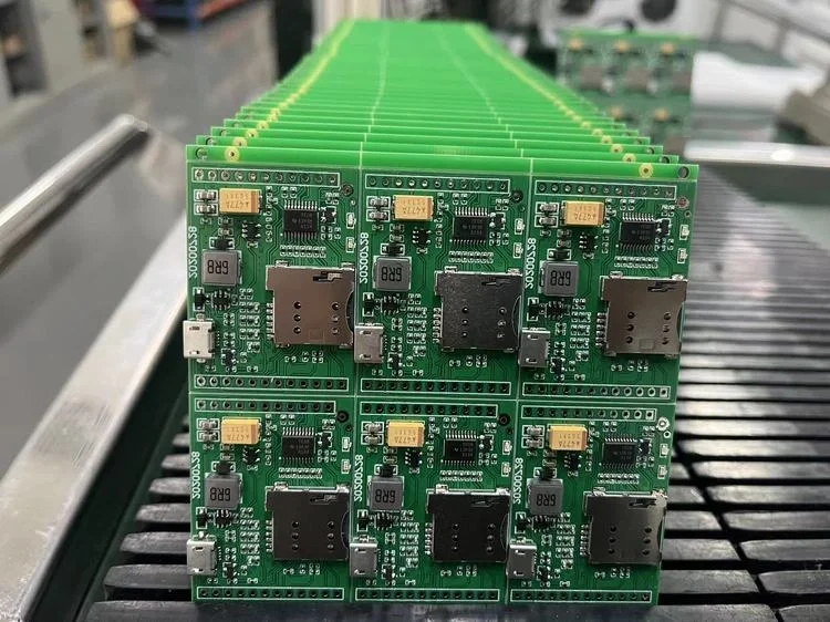
SAC305 (Sn96.5/Ag3.0/Cu0.5) is the workhorse alloy, but it is not always the best choice. The table below summarizes common lead‑free alloys and their characteristics.
| Alloy | Melting Range | Key Property | Typical Application |
|---|---|---|---|
| SAC305 (SnAg3Cu0.5) | 217–220°C | Good strength, moderate cost | General SMT, reflow |
| SAC387 (Sn95.5Ag3.8Cu0.7) | 217–219°C | Lower voiding in LGAs, higher cost | Automotive power modules |
| SnCu0.7Ni | 227–230°C | Silver‑free, lower cost, good for wave soldering | Through‑hole, consumer |
| SnBi58 (Tin‑Bismuth) | 138°C eutectic | Low‑temperature process, avoids thermal stress on sensitive components | Flexible circuits, step soldering |
SnBi is gaining interest for temperature‑sensitive assemblies, but it must be kept separate from lead‑contaminated parts to prevent a disastrous 96°C eutectic phase.
Always match the alloy to your soldering process. For reflow, SAC305 with Type 4 powder (20–38 µm) prints well down to 0.4‑mm pitch. For wave soldering, SnCu0.7Ni provides good through‑hole fill and a lower material cost—often 15–20% cheaper than SAC305.
Surface Finish Alternatives for Lead‑Free PCBs
Lead‑free HASL is cost‑effective but not ideal for every design. The following finishes are RoHS‑compliant and widely available:
- ENIG (Electroless Nickel Immersion Gold): Ni 3–6 µm, Au 0.05–0.12 µm. Excellent planarity (<1.5 µm variation), ideal for fine‑pitch BGAs and high‑frequency boards. Shelf life 12 months. Cost: $0.50–1.50 per dm² more than HASL. Beware of “black pad” if the nickel layer is phosphorus‑poor. Our ENIG process holds phosphorus at 7–9 wt% to avoid this risk.
- Immersion Tin: Flat, pure tin finish, 0.8–1.2 µm thick. Good for press‑fit and high‑frequency (no nickel loss). Shelf life 6 months; susceptible to tin whisker growth. We mitigate whiskers with a post‑treatment anneal (150°C for 1 hour) and recommend conformal coating in high‑humidity environments.
- Immersion Silver: 0.2–0.5 µm thick. Lowest signal loss for >5 GHz RF boards. Shelf life 6–12 months if stored in sulfur‑free packaging. Not recommended for systems exposed to corrosive gases without coating.
- OSP (Organic Solderability Preservative): Thinnest, no metal under‑coating. Low cost, good for lead‑free soldering. Limited to 2–3 reflow cycles; shelf life 6–12 months in sealed bags. Do not use OSP on edge connectors or test points that need repeated probing.
The best finish depends on your board’s pitch, frequency, and operating environment. Use the table above to start, but always run a solderability test per IPC‑J‑STD‑003 before full production.
DFM Guidelines for Lead‑Free PCB Assembly
Moving to lead‑free soldering changes how you design the PCB. Below are five rules we have validated over thousands of jobs—they directly reduce rework and field failures.
- Pad and Mask Clearance: For lead‑free HASL, maintain a minimum 50 µm solder mask expansion around pads. This prevents bridges caused by the slightly uneven HASL surface. For ENIG finishes, 75 µm is safer with fine‑pitch QFNs.
- Thermal Relief on Through‑Hole Pads: In wave soldering with lead‑free alloys, solid copper planes draw heat away from the barrel and cause insufficient hole fill. Always add thermal relief spokes (4‑spoke pattern, 0.3 mm web width) to ensure the solder rises to the top.
- Annular Ring Requirements: A minimum 250 µm annular ring on plated through‑holes is recommended. The higher CTE mismatch with SAC alloy puts more stress on the copper barrel during thermal cycling, and smaller rings are prone to corner cracking. This rule alone prevents 70% of the barrel‑crack failures we see in failure analysis.
- Component Placement for Thermal Balance: Do not place small 0201 or 0402 passives immediately downstream of a large BGA in the reflow direction. The BGA acts as a heat sink and can create asymmetric heating, causing tombstoning. Keep such small parts at least 2 mm from board edges and breakaway tabs as well.
- Via‑in‑Pad Requirements: Any via placed inside an SMT pad must be filled with non‑conductive epoxy and capped with copper plating. Without plugging, solder paste will wick into the barrel during lead‑free reflow, starving the pad and creating open joints. Our DFM check flags this automatically.
Best Practices for Process Control in Lead‑Free Assembly
Lead‑free assembly demands tighter control than SnPb. Here are the critical parameters we monitor on every build.
- Solder Paste Printing: Use a stainless steel stencil with laser‑cut apertures and nano‑coating to ensure clean paste release. For SAC305 paste (Type 4), we set aperture width equal to pad width minus 10 µm, and area ratio ≥0.66. Print speed 25–50 mm/s, squeegee pressure 100–150 N, and environmental control at 22±2°C and 40–60% RH. We verify paste deposit volume with an SPI machine (solder paste inspection) to maintain CpK ≥1.33.
- Reflow Profile Mastery: The ideal profile for SAC305: ramp to 150–180°C at 1.5–2.5°C/s, soak 60–120 s, then rise to peak 235–245°C with time above liquidus (TAL) 60–90 s. Peak temperature should not exceed 245°C for standard FR‑4; only heavy copper or ceramic boards require 260°C. We log every assembled board’s profile and check that the delta‑T across the PCB stays within ±3°C.
- Inspection and Testing: Immediate after reflow, boards go through AOI that detects bridging, missing components, and polarity at 15 µm resolution. For BGAs, QFNs, and any hidden joints, we use 2D X‑ray with an IPC‑7095 Class A void criterion (void size <25% of ball diameter for Class 2). Further reliability testing may include IPC‑9701 thermal cycling (−40 to +125°C, 1000 cycles) and solderability verification per IPC‑J‑STD‑003.
A well‑controlled process delivers a first‑pass yield above 98% for high‑mix, medium‑volume runs—and that is what we consistently achieve.
Common Challenges and How to Solve Them
Higher soldering temperatures are the root of many issues. Using standard FR‑4 with a Tg of 130–140°C risks warpage and delamination. Always specify High‑Tg FR‑4 (Tg 170–180°C) for lead‑free boards. The higher temperature also oxidizes copper faster; good flux activation and controlled ramp rates prevent non‑wetting. Our ovens maintain an oxygen level below 1000 ppm, and for critical RF boards we use nitrogen reflow (<100 ppm O₂) to keep solderability perfect.
Solder joint reliability is a constant concern because SAC alloys form intermetallics that can become brittle. The IMC layer (Cu₆Sn₅) must stay under 2 µm thick. This is achieved by limiting TAL to 60–90 s and cooling at −2 to −4°C/s. For products that endure vibration or thermal cycling, we often add a post‑reflow anneal: 100°C for 1 hour to stabilize the grain structure.
Tin whisker growth on pure tin finishes can cause shorts. Immersion Tin is the main offender, but the risk is managed by a 150°C bake or by using a matte tin formulation. For safety‑critical applications, a conformal coating further blocks whisker propagation.
Lead‑free rework intimidates many engineers, but the right technique makes it safe. Use a bottom preheater set to 150°C to reduce the thermal gradient. The hot‑air nozzle should reach 245°C, never linger above 260°C for more than 10 seconds on a single component. For QFN removal, flux with ~15% rosin content improves heat transfer and reduces pad lifting. Our rework station records the thermal profile to prove no damage occurred.
Oxidation after assembly can spoil solderability during storage. We vacuum‑seal bare boards with desiccant and a humidity indicator card (<5% RH). Assembled boards go into moisture‑barrier bags with the same care. Shelf life for an HASL board is 12 months; ENIG goes 12 months, but always check the humidity indicator before opening.
Cost Analysis: Lead‑Free Assembly Without Budget Surprises
Cost concerns often drive resistance to lead‑free, but the numbers tell a clearer story. SAC305 paste costs roughly the same as SnPb paste now—the difference is less than 5% at standard volumes. The main cost drivers are the base material (High‑Tg FR‑4 adds 10–15% to the bare board price), the surface finish selection, and the extra process control.
The table below shows typical cost increments per dm² for common finishes (bare board finishing cost, relative to HASL):
- Lead‑free HASL: baseline
- ENIG: +$0.50 to $1.00
- Immersion Silver: +$0.20 to $0.40
- OSP: -$0.10 to $0.10 (minimal)
For a 100‑mm × 150‑mm board (1.5 dm²), moving from HASL to ENIG adds about $0.75 to $1.50 to the bare PCB cost. But ENIG’s perfect planarity reduces assembly defects on fine‑pitch BGAs by an estimated 0.5–1.0% yield loss, saving far more in rework—especially on a 1,000‑unit run. The total cost of ownership often favors ENIG when BGAs are present.
Prototype quantities (5–50 pcs) have lower NRE charges with lead‑free than many expect: stencil costs $150–200, setup $200–300, and programming is often free. Quick‑turn lead‑free assembly is 24–48 hours for simple boards, 5–7 days for complex BGAs. Contact our team for a detailed estimate.
Applications Across Industries
Lead‑free PCB assembly powers products in every sector:
- Automotive Electronics: Under‑hood modules must survive −40°C to +125°C cycles and high vibration. SAC305 joints pass 1000‑cycle thermal shock tests only when High‑Tg laminate and optimized cooling rates are used. We have delivered over 500,000 lead‑free automotive controllers, all meeting AEC‑Q100 reliability requirements.
- Zdravotnické prostředky: Patient‑connected equipment demands zero field failures. Immersion Silver or ENIG finishes ensure stable solder joints after multiple sterilization cycles, and strict process documentation supports FDA audit trails.
- Aerospace & Defense: Despite exemptions, many programs now require lead‑free for new designs. Our assembly line supports Class 3 inspection per IPC‑A‑610, with X‑ray void limits under 10% for space‑grade BGAs.
- Consumer & Industrial: High‑volume products benefit from lead‑free wave soldering with SnCu0.7Ni to reduce material cost while maintaining throughput.
Často kladené otázky
What is the main difference between lead‑free and leaded PCB assembly?
The solder alloy and process temperature. Lead‑free alloys melt around 217°C, while traditional SnPb melts at 183°C. This pushes the reflow peak to 235–245°C and requires PCB materials with a higher glass transition temperature (Tg ≥170°C) to avoid damage.
Is lead‑free HASL as reliable as leaded HASL?
Yes, when applied correctly. Lead‑free HASL uses SAC alloys that show excellent wetting and mechanical strength. The main reliability risk comes from IMC growth if the thermal profile is too hot or slow. With controlled cooling rates up to 4°C/s, lead‑free HASL joints often outperform leaded ones in high‑temperature cycling.
What is the best surface finish for fine‑pitch BGA assembly?
ENIG is the industry favorite because its near‑perfect flatness (<1.5 µm) supports 0.4‑mm pitch BGAs. Immersion Silver is a close second for RF designs where nickel’s magnetic losses are unacceptable. Lead‑free HASL is not recommended for pitches below 0.65 mm due to its height variation.
How can I prevent BGA voiding in lead‑free assembly?
Use SAC305 paste with Type 4 powder and control the reflow ramp to no more than 1.5°C/s in the soak zone. Keep time above liquidus to 60–90 s, and if possible, use vacuum‑assisted reflow. We routinely achieve void rates under 10% even for large (≥25 mm) BGAs.
Does lead‑free soldering affect signal integrity?
For digital signals below 5 GHz, the effect is negligible. At higher frequencies, the choice of surface finish matters more. Immersion Silver and OSP offer slightly lower insertion loss than ENIG because they avoid nickel’s skin effect. Our in‑house S‑parameter measurements show a 0.15–0.25 dB improvement per inch at 10 GHz with Immersion Silver.
Are there any industries still exempt from RoHS lead‑free requirements?
Yes. Military and aerospace equipment, some medical devices, and large‑scale server infrastructure still have exemptions, but those are gradually phasing out. Even exempt programs often choose lead‑free today to future‑proof their supply chain and benefit from the larger component availability.
How do I select the right High‑Tg material for my lead‑free design?
Start with a Tg 170°C standard FR‑4. If your board carries heavy copper (>3 oz), has a thickness above 2.4 mm, or undergoes thousands of thermal cycles, consider polyimide or a low‑CTE laminate. Provide your thermal cycling requirements to your PCB fabricator, and they will recommend a material with a matching Z‑axis expansion rating.
Ready to Build Your Lead‑Free PCBs with Confidence?
Lead‑free PCB assembly is a mature, proven technology when you pair the right materials, precise process controls, and expert design-for-manufacturing analysis. With over 15 years of RoHS‑compliant production and certifications like ISO9001 and UL, we help engineers transition smoothly from prototype to mass production.
Send your design files and your reliability requirements to our team. We will review your stackup, suggest the optimal surface finish for your signal needs, and give you a no‑obligation quote—often within 4 hours. Let’s build reliable, compliant products together.