


















X-Ray Inspection for BGA and Hidden PCBA Joints: What It Finds and What It Cannot
A PCB X-ray inspection can make some solder features under a BGA or other hidden-termination package visible after assembly. It can reveal patterns consistent with bridges, missing or irregular joints, misalignment and voiding that ordinary visual inspection cannot see under the package. It is an image-based inspection method, however: a plausible image does not by itself prove electrical function, long-term reliability or compliance with every acceptance requirement.
For a buyer, the useful question is not simply “Does this assembler use X-ray?” It is which joints will be inspected, for which defect modes, by which method, and what record will determine acceptance. Philifast’s BGA assembly page introduces the assembly context. The inspection plan still needs to be agreed for the actual board and package.
Why BGA joints need a different view
After reflow, the ball grid array sits beneath the component body. A camera looking from above cannot directly see the joint interface. X-rays pass through the assembly and produce contrast from materials with different attenuation, allowing the operator or automated system to examine otherwise hidden structures. Sierra Circuits’ PCB X-ray overview describes this use for hidden connections. Equipment makers such as Omron discuss the range of imaging methods; a particular system’s capability should not be assumed for another factory.
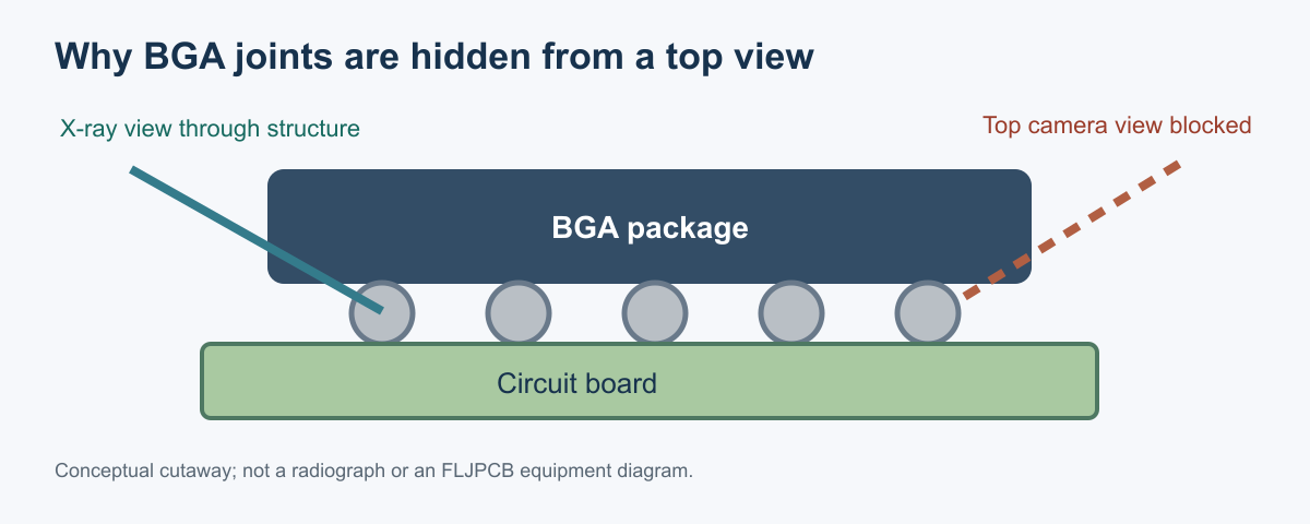
Illustration: The cutaway explains line of sight, not the appearance of a real radiograph.
Findings an X-ray review can support
An appropriate image may show neighboring balls joined by excess solder, a missing ball or obvious nonuniformity, a gross placement offset, or dark regions consistent with voids within a solder joint. The detectability of each feature depends on resolution, view angle, overlapping structures, package design and image interpretation. A 2D projection collapses depth into one image; angled or computed-tomography approaches can help separate overlapping features when available. JLCPCB’s inspection guide explains why 2D and 3D approaches should not be treated as identical.
The same reasoning applies beyond a BGA. A QFN or LGA can hide a large thermal pad and edge terminations; through-hole joints can conceal internal fill. But the image feature and acceptance question change with the package. A dark region under a QFN thermal pad should not be interpreted using a BGA-ball rule. Identify the actual package, pad function and customer criterion before measuring a suspected defect.
| Observed in image | Reasonable next step | What not to conclude automatically |
|---|---|---|
| Apparent bridge between adjacent balls | Review image and relevant package geometry; correlate with electrical test | Every bright overlap is definitely a short. |
| Void within a joint | Measure against an agreed component/product criterion | Any visible void is automatically unacceptable. |
| Irregular or missing ball shape | Compare with nearby joints and placement/reflow records | X-ray alone identifies the root cause. |
| Uniform-looking ball array | Continue required electrical/functional tests | The assembly is guaranteed reliable. |
Acceptance criteria need to be set for the product and the applicable workmanship requirements. A universal void percentage copied from a supplier blog may be inappropriate for a different package, joint, standard or customer specification.
Reading a void without overcalling it
A void is a region inside the apparent solder volume where less X-ray-absorbing material is present. The image may let an operator estimate its projected area, but that is not automatically its three-dimensional volume. Location can matter as much as size: a void at an interface or concentrated in a critical thermal path may need a different evaluation from a small central void. Ask which measurement method and view were used, which joint was measured, and which product or package criterion defined the result. The picture alone does not supply those rules.
Similarly, a “head-in-pillow” condition concerns a poor or incomplete connection between a package ball and printed solder. Some imaging systems and views can help investigate it, but a single top-down 2D image may not unambiguously show the interface. AdvancedPCB’s X-ray guide lists several imaging modes and defect types; the practical lesson is to request a suitable method for the suspected fault rather than assuming every defect on a list is equally visible in every scan.
What X-ray cannot prove
X-ray cannot replace a powered functional test. It may reveal a geometric problem that explains an open or short, but it does not demonstrate that the device boots, communicates or meets performance limits. It also does not guarantee that an apparently well-shaped joint has a sound metallurgical interface or will survive its intended environment. Some defects are ambiguous in a single projection and require a second view, another test or destructive failure analysis.
If metal features overlap in the X-ray path, a projection can make separate structures look connected. A tilted view may help separate them. Computed tomography reconstructs multiple projections into a three-dimensional representation, but it adds inspection effort and is not automatically the right method for routine production. Resolution, scan time and package geometry drive that choice. The supplier should state what it can resolve for the actual board, rather than giving only a machine model or a generic “3D X-ray” label.
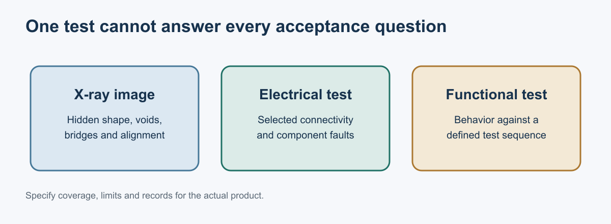
Illustration: Different tests answer different acceptance questions.
That is why X-ray belongs in a layered test plan. Solder paste inspection examines the print before placement; post-reflow AOI checks visible features; X-ray addresses selected hidden features; electrical or functional tests check circuit behavior. Philifast’s PCBA testing guide discusses these related methods. None is a universal substitute for the others.
An electrical test that passes also has limits. It may show continuity at test time without proving a hidden joint’s geometry or fatigue life. Conversely, a suspicious image can trigger a focused electrical check that helps decide disposition. For high-consequence defects, the team may need process records, cross-sectioning or another failure-analysis method. Keep the tests connected to the specific risk instead of treating “X-ray passed” as a global certificate.
Review an image as a sequence of questions
Before judging a joint, confirm that the image belongs to the right product and location. Match the board or panel position, assembly revision, package reference designator and view to the report. A clear image with no unit identity is weak production evidence; an image mapped to a unit but captured from the wrong revision can be actively misleading. Keep original views as well as annotations so another reviewer can see what the software or operator marked.
Next ask what geometry the view can separate. In a two-dimensional projection, features at different heights can overlap. A top-down view is useful for comparing an array pattern, while an angled view may help separate some overlapping geometry; neither view guarantees visibility of every defect. Package pitch, board copper and nearby structures affect contrast and interpretation. If an image cannot resolve a suspected feature, record that limitation and request another view or another method rather than converting uncertainty into a pass.
Describe observations before conclusions. “Several balls show reduced contrast” is an observation; “open joint” is a diagnosis that should be supported by additional evidence. For an apparent bridge, identify the adjacent balls and the view. For a possible missing or irregular joint, compare the relevant row or column and record whether electrical testing supports the concern. For a suspected void, state the measurement method and the specified criterion used. Keep image review separate from final disposition so the customer or designated engineering authority can resolve an ambiguous result.
Do not infer an acceptance limit from a picture
The standard revision and the purchase agreement govern acceptance. As of September 29, 2026, IPC lists IPC-A-610J as its current electronic-assembly acceptance revision and IPC-7095E as the current design and assembly guidance revision for BGA devices. The IPC revision table is the source for current revision status; consult the licensed IPC-A-610J και IPC-7095E documents for the applicable requirements and guidance. A table of contents, training image, equipment software threshold or supplier blog is not a substitute for the invoked standard, customer drawing or agreed product-specific criterion.
In particular, do not assume a general void percentage from an uncited web table applies to every package, ball, design-induced via or end use. The user and manufacturer may need to establish criteria for the product and state how the measurement is made. A criterion should specify the relevant feature, measurement plane or method where applicable, sampling scope, review authority and disposition path. If the order invokes a specific IPC revision, check the actual licensed standard text and applicable clauses; a table of contents or an online summary cannot supply a complete acceptance rule.
A useful review record separates three fields: the feature observed, the acceptance rule applied, and the decision authorized. That separation avoids turning “X-ray inspected” into a blanket compliance claim. If the acceptance reference does not address the exact image finding, hold the affected units and route the question to the design authority. Document whether the outcome is rework, additional inspection, engineering analysis, use-as-is approval or rejection, as applicable to the contract.
Consider a panel where one BGA’s outer row appears different from the interior rows. First verify board position, orientation and whether the same pattern appears on neighboring boards. Then compare the image with the land and package layout, request an alternate view if overlap is suspected, and check relevant electrical results. If the image suggests a recurring process pattern, review the assembly lot and reflow or placement records; if only one unit differs, preserve that unit for focused analysis. This sequence does not force a pass or fail from appearance alone. It defines the next evidence needed and protects the original data while the responsible engineer determines disposition.
For critical products, decide before production whether a borderline finding triggers expanded sampling, a hold on the lot, destructive analysis or customer review. Agree who pays for the additional work and whether it changes delivery timing. The answer depends on the contract and product risk, so write it into the inspection plan rather than improvising after an ambiguous image arrives.
Use X-ray as one part of a planned evidence set. SPI records the print before reflow and cannot show the final hidden joint; ICT or functional testing can answer selected electrical questions but does not show joint geometry. The SPI guide και test-plan guide distinguish those stages. Choose inspection and test based on the failure mode and required decision, and state whether sampling or full inspection is required before quoting.
Specify the evidence before the build
Identify the packages and reference designators to inspect, whether the request covers first articles, samples, failures or every board, and which defect modes matter. Agree on the inspection method, the acceptance reference, how borderline images will be reviewed, what image/report will be retained, and who approves rework or disposition. For dense or high-reliability assemblies, include the package supplier’s guidance and product-specific requirements in that decision.
What a usable report should identify
A report should map an image to the board or panel position, assembly revision, reference designator and inspected joint region. It should state the view or method, the suspected feature, the measurement if one was made, the criterion used, and the disposition. A gallery of unlabelled BGA images cannot tell a buyer whether the inspected devices were sampled from the first article, taken after rework, or drawn from a production lot.
For example, “U4, northeast ball row, board 7 of panel 3: apparent bridge in top-down view; angled view and electrical test requested; hold pending engineering disposition” gives an actionable record. It separates an observation from a verdict. The final record should note who resolved the hold and what changed, if anything, in the assembly process.
Sampling also needs a reason. First-article scans may validate a new package, stencil or reflow setup; periodic sampling may monitor a stable process; a failure investigation may target one suspect board. Complete inspection may be required for some products, but its scope must be specified and quoted. “We use X-ray” does not identify the inspected percentage, locations or acceptance rules.
If you need X-ray evidence from Philifast, ask for the project-specific method and report format in the RFQ. The public site mentions inspection, but it does not establish a universal imaging resolution, scan coverage or void acceptance limit for every order. A precise request produces a more useful answer than the instruction “X-ray all BGAs.”