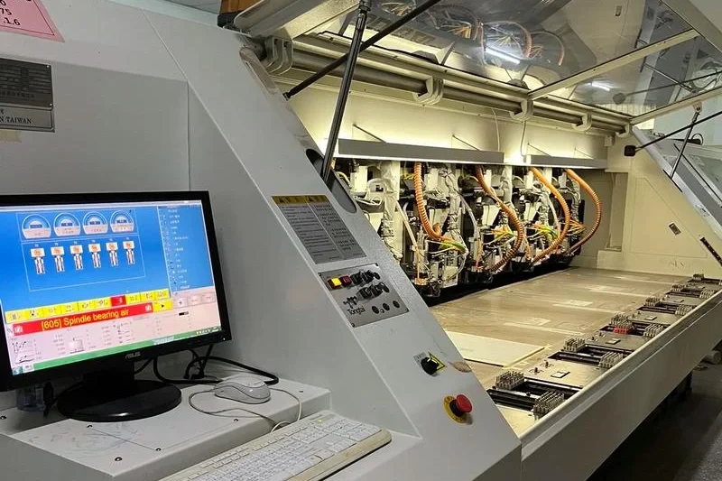
هیچ فرد بزرگی وجود ندارد، تنها تیمهای بزرگ وجود دارند. با همکاری تیم، پروژهٔ اتوماسیون CAM برد مدار چاپی مرحلهٔ اول برای مدیریت خالص و دستکاری مته انجام شد. در ادامه میتوانیم به موتور قوانین PCB بپردازیم. در اینجا دربارهٔ جبران سوراخکاری در مهندسی PCB صحبت میکنم. بهعنوان یک توسعهدهندهٔ مهندسی PCB، باید بدانید این چیست و چرا کار میکند. نکات کلیدی دربارهٔ جبران سوراخکاری را در ادامه مطرح میکنم.
۱. چرا ما اندازههای مته را جبران میکنیم؟
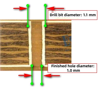
اندازه سوراخها در فایلهای PCB که مشتری ارائه میدهد معمولاً به معنای نهایی اندازه سوراخ. در طول تولید PCB، داخل سوراخها با مس آبکاری میشوند (یا سوراخها پوشش سطحی مانند HASL، ENIG، OSP و غیره دریافت میکنند). این کار باعث کوچکتر شدن سوراخ میشود. برای اطمینان از اینکه اندازه نهایی سوراخ با نیازمندی مطابقت دارد، مرحله CAM اندازه مته را اصلاح میکند. این جبران مته است.
مثال واقعی:
قطر نهایی سوراخ: ۱.۰۰ میلیمتر. پرداخت سطح: ENIG (ضخامت نیکل ۲٫۵۴ میکرومتر، ضخامت طلا ۰٫۰۲۵۴ میکرومتر). طبق IPC کلاس II، ضخامت متوسط مسی آبکاریشده است ۲۰ میکرومتر. اگر ما استفاده کنیم 0.10 میلیمتر بهعنوان مقدار غرامت، تیم CAM یک را انتخاب خواهد کرد ۱.۱۰ میلیمتر متهٔ دریل.
۲. چگونه جبران خسارت حفاری را انجام میدهیم؟
ابتدا، در مورد سه پارامتر کلیدی جبرانپذیری مته، شفاف باشید:
(1) افزایش متهٔ سوراخکاری,
(2) ارزش جبران,
(3) آستانهٔ گامافزایی (مقدار پیشرفت).
این سه مشخص میکنند که چگونه غرامت اعمال شود.
۱) گام متهٔ سوراخکاری
این بستگی به متههای دریلی دارد که شرکت خریداری میکند. افزایش رایج در صنعت است ۵۰ میکرومتر. اندازههای متداول مته از 0.10 میلیمتر به ۶٫۳۵ میلیمتر. معمولترین گام کوچک بین متهها است 0.05 میلیمتر. بنابراین کتابخانهٔ درایو دارای اندازههایی مانند 0.10 میلیمتر، 0.15 میلیمتر، 0.20 میلیمتر، 0.25 میلیمتر, و غیره.
۲) ارزش جبرانی
تیم فرآیند قواعد جبران را بر اساس نتایج آزمونهای کارخانه تعیین میکند. مقادیر جبران در صنعت چندان متفاوت نیستند. قواعد رایج:
-
بردهای دارای HASL (قوطی اسپری): جبران ۰.۱۵ میلیمتر.
-
بردهای بدون HASL (ENIG، حمام قلع، OSP و غیره): جبران ۰.۱۰ میلیمتر.
۳) آستانهٔ گامبالا (مقدار پیشرفت)
تیم فرآیند همچنین استراتژی انتخاب مته را تعیین میکند، مشابه یک قاعده گرد کردن. برای مثال، وقتی گام افزایش است ۲۰ میکرومتر, ، اگر باقیمانده تقسیم بر افزونه برابر باشد ≥ ۲۰ میکرون, اگر اندازه گرد شده ۵۰ میکرومتر باشد، در غیر این صورت اندازه کوچکتر را حفظ میکنید.
مثال:
اندازه نهایی سوراخ = ۱٫۰۲۵ میلیمتر, ، جبران خسارت = 0.10 میلیمتر, ، بنابراین اندازه جبرانشده = ۱٫۱۲۵ میلیمتر. اما وجود ندارد ۱٫۱۲۵ میلیمتر تمرین در کتابخانه. از قانون گام صعودی استفاده کنید. باقیمانده 1.125 میلیمتر در مقایسه با گام 0.05 میلیمتر است. ۲۵ میکرومتر. از آنجا که ۲۵ میکرومتر > ۲۰ میکرومتر, ، تا ۵۰ میکرومتر گرد کنید و یک را انتخاب کنید ۱٫۱۵ میلیمتر تمرین.
نمونههای واقعی جبران خسارت حفر
فرض کنید: گام مته = ۵۰ میکرومتر, ، آستانهٔ ارتقاء = ۲۰ میکرومتر
| سوراخ اصلی | جبران | پس از جبران خسارت | بخش صحیح | باقیمانده | سوراخکاری انتخاب شد |
|---|---|---|---|---|---|
| ۱٫۰۲۵ میلیمتر | 0.10 | ۱٫۱۲۵ میلیمتر | 1.10 | 0.025 میلیمتر | ۱٫۱۵ میلیمتر |
| ۱٫۰۱۶ میلیمتر | 0.10 | ۱٫۱۱۶ میلیمتر | 1.10 | 0.016 میلیمتر | ۱.۱۰ میلیمتر |
چگونه اندازه مته انتخابشده را محاسبه کنیم
اندازهٔ سوراخ جبرانی را با استفاده از گام مته به بخش صحیح و بخش باقیمانده تقسیم کنید:
بگیر ۱٫۱۲۵ میلیمتر بهعنوان مثال:
۱٫۱۲۵ / ۰٫۰۵ = ۲۲٫۵ → به زیر ۲۲ گرد میشود → بخش صحیح = ۲۲ × ۰٫۰۵ = ۱.۱۰ میلیمتر.
باقیمانده = 1.125 % 0.05 = 0.025 میلیمتر.
سپس باقیمانده را با آستانه افزایش گام (برای مثال، ۲۰ میکرومتر) مقایسه کنید:
-
اگر باقیمانده > آستانه، اندازه مته = بخش صحیح + 0.05 میلیمتر.
-
اگر باقیمانده ≤ آستانه باشد، اندازه مته = بخش صحیح + 0.00 میلیمتر.
خلاصهای درباره آستانه پلهای
وقتی گام حفر است ۵۰ میکرومتر, آستانهٔ افزایش گام، حیاتی است. این آستانه اصلاح دوم اندازهٔ متهٔ جبرانشده را انجام میدهد. این آستانه تعیین میکند که آیا باید “افزایش گام” دهد یا “باقی بماند”. تغییر این آستانه مستقیماً اندازهٔ متهٔ انتخابی را تغییر میدهد.
نمونههای بیشتر (افزایش سوراخکاری = ۵۰ میکرومتر):
| سوراخ اصلی | جبران | بعد از محاسبه. | عدد صحیح | باقیمانده | آستانهٔ پلهای | تمرین |
|---|---|---|---|---|---|---|
| ۱٫۰۲۲ میلیمتر | 0.1 | ۱٫۱۲۲ میلیمتر | 1.10 | 0.022 میلیمتر | 0.02 | ۱٫۱۵ میلیمتر |
| ۱٫۰۲۲ میلیمتر | 0.1 | ۱٫۱۲۲ میلیمتر | 1.10 | 0.022 میلیمتر | 0.025 | ۱.۱۰ میلیمتر |
دیدگاه شخصی درباره تعیین آستانه افزایش پلهای
مزایا و معایب: پس از جبران، اگر سوراخ نهایی کمی بزرگتر باشد، حداقل میتوان قطعه را وارد کرد. اگر سوراخ خیلی کوچک باشد، قطعه قابل وارد شدن نیست. بنابراین معمولاً آستانهٔ افزایش را روی ۲۰ میکرومتر به جای ۲۵ میکرومتر. انتخاب دقیق باید با هر فرایند و مقدار جبران مطابقت داشته باشد.
در ترکیب با ارزش جبران: برای بردهایی با HASL که جبران آن 0.15 میلیمتر, شما قبلاً کمی بیش از حد جبران میکنید و سوراخهای نهایی کمی بزرگتر میشوند. در این صورت، آستانهٔ افزایشیافتهٔ ۲۵ میکرومتر این هم میتواند کار کند. هنگام انتخاب مته، از قانون “نزدیکترین” استفاده کنید.
۳. چگونه اطمینان حاصل کنیم که پس از جبران، اندازه نهایی حفره با الزامات مطابقت دارد؟
روش اول: خرید متههای مخصوص
افزایش استاندارد مته است ۵۰ میکرومتر (گامهای ۰٫۰۵ میلیمتری مانند ۱٫۰۰، ۱٫۰۵، ۱٫۱۰ و ۱٫۱۵ میلیمتر). با تلرانس PTH برابر ±۳ میل، یک مجموعه متهٔ ۵۰ میکرومتر میتواند این تلرانس را پوشش دهد. اگر تلرانس کمتر از این باشد، از متههای ویژه استفاده کنید.
مثال ۱ — مقایسه افزایشهای ۵۰ میکرومتر در مقابل ۲۵ میکرومتر:
سوراخ اصلی = ۰.۹۲۲ میلیمتر, ، جبران خسارت = 0.10 میلیمتر, ، اندازهٔ جبرانشده = ۱٫۰۲۲ میلیمتر.
| اصلی | جبران | جبرانشده | افزایش | سوراخکاری انتخاب شد |
|---|---|---|---|---|
| 0.922 | 0.10 | 1.022 | 0.05 (50 میکرومتر) | 1.05 |
| 0.922 | 0.10 | 1.022 | 0.025 (25 میکرومتر) | 1.025 |
تفاوت: 1.050 − 1.022 = 0.028 میلیمتر؛ 1.025 − 1.022 = 0.003 میلیمتر. هرچه تفاوت کمتر باشد بهتر است، بنابراین ۱٫۰۲۵ میلیمتر (افزایش ۲۵ میکرومتر) بهتر است.
مثال ۲ — ۵۰ میکرومتر در مقابل متهٔ ویژه:
سوراخ اصلی = 0.611 میلیمتر, ، جبران خسارت = 0.10 میلیمتر, ، جبرانشده = ۰.۷۱۱ میلیمتر.
| اصلی | جبران | جبرانشده | افزایش / نوع | سوراخکاری انتخاب شد |
|---|---|---|---|---|
| 0.611 | 0.10 | 0.711 | 0.05 (50 میکرومتر) | 0.70 |
| 0.611 | 0.10 | 0.711 | تمرین ویژه | 0.711 |
تفاوت: 0.700 − 0.711 = −0.011 میلیمتر؛ 0.711 − 0.711 = 0.000 میلیمتر. هرچه اختلاف کوچکتر باشد بهتر است. بنابراین دریل ویژه ۰.۷۱۱ میلیمتر بهترین است.
روش ۲: بهبود فرآیند و تجهیزات
-
یک مرحلهٔ دوم آبکاری برد اضافه کنید تا ضخامت نامنظم ناشی از توزیع الگو کاهش یابد.
-
از حک مستقیم عکس منفی استفاده کنید و کل برد را آبکاری کنید تا ضخامت نامتوازن مس کاهش یابد.
-
چگالی جریان را کاهش دهید (معمولاً ۱۹ ASF)؛ کاهش اندکی در چگالی جریان میتواند یکنواختی آبکاری را بهبود بخشد اما زمان آبکاری را افزایش میدهد.
-
به یک خط آبکاری افقی ارتقا دهید. خطوط آبکاری عمودی اغلب در لبهی سوراخ مس ضخیمتر و در مرکز سوراخ مس نازکتری ایجاد میکنند، بهویژه برای سوراخهایی با نسبت ارتفاع به قطر بالا. یک خط افقی میتواند این مشکل را کاهش دهد.
روش ۳: بهبود استراتژیهای CAM
-
برای سوراخها در نواحی مسی ایزوله، یک مرحله اضافی جبران اعمال کنید. نواحی ایزوله مس کمتری دارند، بنابراین در حین آبکاری چگالی جریان موضعی بالاتری پیدا کرده و ضخامت مس بیشتری مییابند؛ جبران اضافی این موضوع را جبران میکند.
-
برای طرحهایی که ردهای مسی در یک سمت متراکم و در سمت دیگر پراکنده هستند (برای مثال برد تغذیه)، سمت پراکنده را به داخل و سمت متراکم را به خارج قرار دهید و از پانلسازی معکوس استفاده کنید. در حین آبکاری پانل، نواحی نزدیک لبه برد چگالی جریان بالاتری دریافت کرده و آبکاری ضخیمتری میشوند. پانلسازی معکوس به متعادلسازی توزیع آبکاری کمک میکند.
-
وقتی مساحت مس روی سطح بالا و پایین برد بهطور قابلتوجهی متفاوت است، از پانلبندی مثبت/منفی (یین-یانگ) استفاده کنید. ناحیه نامتوازن مس باعث ایجاد ویای “دهانقوچی” میشود؛ هرچه برد ضخیمتر و مس بیشتر باشد، این اثر بدتر میشود؛ پانلبندی یین-یانگ به متعادلسازی توزیع مس کمک میکند.
-
برای سوراخهای ناحیهٔ ایزوله نزدیک لبهٔ برد یا شکافها، نواحی برداشت مس یا پدهای مسی را نزدیک لبه یا شکاف اضافه کنید. سوراخهای ایزوله ممکن است به دلیل ضخامت زیاد آبکاری خیلی کوچک شوند؛ مس اضافی اطراف آنها تراکم جریان موضعی را کاهش داده و آبکاری را متعادل میکند.
۴. چه میزان غرامت لازم است و چگونه محاسبه میشود؟
مقادیر جبران از آزمونهای فرآیند بهدست میآیند. در زیر یک مجموعه از تغییرات اندازهگیریشده در اندازه سوراخ پس از مراحل مختلف آورده شده است (دادهها از یک گزارش):
جریان فرآیند: حفاری مکانیکی → آبکاری مس غوطهوری → آبکاری الکتریکی → انتقال الگو → حکاکی → AOI → لایه مرطوب → HASL
پارامترهای فرآیند:
-
مته: قطر مته ۰٫۹۵ میلیمتر، تیزکاری مجدد ۳ بار، جبران مته ۰٫۱۵ میلیمتر؛;
-
آبکاری: ضخامت مس ≥ ۱۸ میکرومتر، میانگین ≥ ۲۰ میکرومتر؛;
-
HASL: نیازمندی سوراخ نهایی ۰.۸۰ میلیمتر، تلرانس ±۰.۰۸ میلیمتر (۳ میل)؛;
-
آزمایش: ۱۰ پنل، برش خورده از گوشه، ضخامت تخته ۲٫۰ میلیمتر.
اندازه سوراخ به صورت پلهای تغییر میکند.
۱) پس از سوراخکاری — اندازهگیری اندازههای حفرهها
-
مجموعاً ۱۹۲۰ حفره آزمایش شدند (۱۰ پنل، هر کدام ۳۸۴ حفره). نمونه: ۲۰۰ حفره (۲۰ حفره در هر پنل). دامنه حفرهها: ۰.۹۳–۰.۹۴ میلیمتر, متوسط ۰٫۹۳۱ میلیمتر.
(سپس یک فهرست طولانی از مقادیر نمونهبرداریشده، که بیشترشان ۰.۹۳ یا ۰.۹۴ بودند.)
۲) پس از آبکاری الگویی — ضخامت مس
-
برای هر پنل، ده سوراخ را آزمایش کنید. دامنه ضخامت مس ۱۸–۳۱ میکرومتر, ، قطر ≥۱۸ میکرومتر و میانگین ≥۲۰ میکرومتر.
(سپس مقادیر نمونهٔ ضخامت مس)
۳) پس از آبکاری الگویی — اندازهٔ سوراخ
-
مجموع ۱۹۲۰ حفره، نمونه ۲۰۰. محدوده حفرهها: 0.84–0.88 میلیمتر, متوسط 0.858 میلیمتر.
(سپس مقادیر نمونهٔ فراوان، عمدتاً ۰.۸۵–۰.۸۸.)
۴) پس از HASL — اندازه سوراخ
-
مجموع ۱۹۲۰ حفره، نمونه ۲۰۰. محدوده حفرهها: 0.82–0.86 میلیمتر, متوسط 0.836 میلیمتر.
(سپس مقادیر نمونهٔ فراوان)
خلاصه آزمون
| مرحله | محدودهٔ سوراخ | حفرهٔ متوسط |
|---|---|---|
| پس از سوراخکاری | ۰.۹۳–۰.۹۴ میلیمتر | ۰٫۹۳۱ میلیمتر |
| پس از آبکاری مس | 0.84–0.88 میلیمتر | 0.858 میلیمتر |
| پس از HASL | 0.82–0.86 میلیمتر | 0.836 میلیمتر |
نتیجهگیری: برای بردهای HASL، جبران متهٔ 0.15 میلیمتر یک “جبران بیش از حد” است و باعث میشود سوراخهای نهایی بزرگتر شوند. بهترین مقدار جبران در این آزمون است 0.125 میلیمتر.
۵. پیادهسازی کد جبران خسارت (قوانین)
-
قوانین جبران خسارت و صعود پلهای
| جنبه | سوراخ تکمیلشده | نهایتکاری سطح | ضخامت تخته | آستانهٔ پلهای | اگر از طریق مس کمتر از ۲۶ میکرومتر | ۲۶–۳۷ میکرومتر | ۳۷–۴۷ میکرومتر | ۴۷–۶۷ میکرون | ۶۷–۸۶ میکرومتر |
|---|---|---|---|---|---|---|---|---|---|
| نسبت ضخامت < ۱۲:۱ | ≤ ۱٫۹۰ میلیمتر | HASL (دارای سرب یا بدون سرب) | ≥ ۳.۵ میلیمتر | 0.01952 | ۵ مایل | ۶ مایل | ۷ مایل | ۸ مایل | ۹ مایل |
| نسبت ضخامت < ۱۲:۱ | ≤ ۱٫۹۰ میلیمتر | HASL (دارای سرب یا بدون سرب) | کمتر از ۳.۵ میلیمتر | 0.01952 | ۴.۵ میل | ۵.۵ میل | ۶.۵ میل | ۷.۵ میل | ۸.۵ میل |
| نسبت ضخامت < ۱۲:۱ | ≤ ۱٫۹۰ میلیمتر | پایانهای دیگر | / | 0.01952 | ۴ مایل | ۵ مایل | ۶ مایل | ۷ مایل | ۸ مایل |
| نسبت ضخامت < ۱۲:۱ | ۱٫۹۰ میلیمتر | HASL | / | 0.0246 | ۵.۵ میل | ۶.۵ میل | ۷.۵ میل | ۸.۵ میل | ۹.۵ میل |
| نسبت ضخامت < ۱۲:۱ | ۱٫۹۰ میلیمتر | پایانهای دیگر | / | 0.01952 | ۴.۵ میل | ۵.۵ میل | ۶.۵ میل | ۷.۵ میل | ۸.۵ میل |
| نسبت ضخامت ≥ ۱۲:۱ | تمام سوراخها | HASL | / | 0.0246 | ۵.۵ میل | ۶.۵ میل | ۷.۵ میل | ۸.۵ میل | ۹.۵ میل |
| نسبت ضخامت ≥ ۱۲:۱ | تمام سوراخها | پایانهای دیگر | / | 0.01952 | ۵ مایل | ۶ مایل | ۷ مایل | ۸ مایل | ۹ مایل |
-
سایزهای متهٔ ویژه (اگر تلرانس کمتر از ۳ میل باشد، از متههای ویژه استفاده کنید؛ یا اگر گام ۲۵ میکرومتر باشد، از قاعدهٔ متهٔ نزدیکتر استفاده کنید)

