
Flexible circuits · Component assembly
Flex PCB Assembly Services
Components and connectors assembled on flex circuits built to fit your product.
FLJ supplies populated FPC and rigid-flex assemblies, from bare circuit manufacture and component sourcing through supported SMT processing, connector installation and product-specific testing.

Assembled Flex Circuits and Interconnects
FLJ supplies flexible circuits as mounted assemblies, with components installed at selected pads while intended flex areas remain flexible. An assembly may terminate at a board interface or connect separate rigid sections of a product. Its form depends on component locations, mating needs, and areas that must bend.
Surface-mount or leaded parts are soldered at designated locations on a single- or double-sided FPC. The mounted area can be supported during assembly while the free span follows its intended route; mounting parts does not make the whole circuit rigid.
A flex tail or soldered connector provides an interface to another board or product. Pin mapping alone does not establish fit: keying, orientation, cable exit, routing, support, and room to mate must suit the installed path.
In an integrated rigid-flex construction, components mount on rigid circuit regions linked through the flex layers. Those rigid regions contain electrical routing and interconnects. A bonded stiffener instead provides local mechanical support.
FLJ can manufacture the bare circuit, mount the components and connectors, and perform the inspection and testing defined for the build. Component locations, mating interfaces and free-bend areas together define the assembly we prepare for your product.
Flex PCB Assembly Process
Thin circuits need a stable working surface before paste can be printed or parts placed. Temporary support holds the assembly in position through the operations that need it, then releases the finished flex.

Preparing and Supporting the Flex Circuit
FLJ checks the condition of moisture-sensitive parts and follows the device maker’s handling instructions, taking account of their packaging and time outside controlled storage. The flex circuit needs a separate material check: its film, coverlay, adhesive, stiffener and surface finish must tolerate the planned preparation and soldering operations. We select handling and any drying conditions for those actual materials, including the temporary fixture where used.
A temporary carrier positions the flex and supports the regions being printed, populated and soldered. Its locating features and attachment must hold the circuit against the process reference without obstructing the work. Carrier shape and fixing method follow the panel and assembly sequence; after the supported operations, the circuit is released for subsequent work or installation.
Solder Paste Printing and Component Placement
During solder paste printing, we register the flex and stencil so the apertures align with the intended pads. Support beneath the print area maintains stencil contact as the paste is deposited and the stencil separates. A local lift or shift changes that contact and release, affecting the deposit that will form the joint.
Placement then matches each component and its feeder or tray identity to the board reference, footprint, position, and rotation, including polarity and do-not-populate locations. The carrier supports the circuit as parts are placed; local height and nearby components also affect access and support. We set up placement around that supported geometry and the parts being fitted.
Reflow Soldering and Second-Side Assembly
During reflow, solder melts, wets the component termination and pad, then solidifies into a joint. A carrier changes the thermal load around the thin circuit, while mounted parts add local thermal mass. We prepare reflow for this combined assembly, considering how the supported regions heat and the temperature limits of the connectors, adhesive, finish and components. The programmed oven conditions have to be considered alongside the assembly’s thermal response at the joints.
For a second side, the first-side components and joints are already part of the workpiece. Their height, location, and prior heat exposure constrain how the flex can be supported, positioned, and heated again. We account for that populated shape when preparing support for the next operation, then check the assembled connections against the product requirements. This keeps the next operation compatible with the components and joints already fitted.
Stiffeners, Connector Fit and Bend-Zone Protection
Production support and finished-product support do different jobs. The table separates the carrier used during assembly, a bonded stiffener that remains on the flex, and a routed rigid region within a rigid-flex board. Their boundaries determine which areas stay supported and where the free flex can follow the installed route.
| Support feature | When it does its job | In the finished assembly |
|---|---|---|
| Temporary carrier | Provides a stable reference and support for assembly operations on a flexible circuit. | Removed after the supported operations; it is not permanent product reinforcement. |
| Bonded stiffener | Supports a local component, connector, contact end or mounting area. | Remains attached locally; its edge marks a transition to the flex span. |
| Integrated rigid circuit region | Provides a rigid electrical region within a rigid-flex construction. | Remains part of the circuit, including its routed layers and interconnects. |
Permanent Reinforcement and Mating Interfaces
For a connectorized assembly, fit depends on the actual mating interface. At an insertion contact end, the exposed copper face, contact pattern, outline and insertion orientation must match the specified connector. The finished local thickness also matters: copper and finish, retained protective layers, adhesive and reinforcement can all contribute. We match the finished contact-end construction to the selected connector requirements, including the full local thickness and the side carrying the exposed contacts.
For a connector soldered to flex, local reinforcement can support its footprint against assembly or installation loads. Our assembly-access review considers the footprint, reinforcement side and extent, and room to place, solder and reach the connector in the populated layout.
Keeping Components and Joints Clear of Active Bends
Keep components, solder joints and connector attachment areas in supported regions where the layout allows, leaving the intended flex span available to bend. A stiffener edge changes where flexing begins; repeated movement across that transition or a joint can concentrate strain. Consider the outline, support boundary and installed route together.
A circuit that bends once into a fixed installed position has a different duty from one that moves repeatedly in service. The flex construction, bend path and motion need to be defined for the actual assembly; no single bend radius or cycle expectation applies to every design. For connectorized flex, account for exit direction and cable reaction as well as pin mapping, so movement does not load the soldered or mated interface.
Inspecting and Testing the Flex Assembly
FLJ inspects the populated assembly against the required component and joint criteria, along with the flex body, exposed contacts, coverlay edges and reinforcement features that affect installation. Electrical and functional checks then address the paths and operating responses specified for the product.
Solder Joints, Alignment and Flex Condition
Support the flex while checking alignment, terminations, contacts, and free regions. Optical or manual inspection can assess accessible features. Solder-paste inspection applies at printing, while X-ray may be selected for hidden joints that need evaluation. A surface image cannot establish a hidden joint’s condition. Judge findings against package and product criteria, then recheck after correction.
Supported Electrical and Functional Tests
Continuity or isolation checks assess selected electrical paths at the time of measurement. We plan test access and local support at the probe or mating point so contact force does not bow or stretch unsupported flex. Clearance, return paths and contact quality matter to the measurement as well as the presence of an exposed pad.
Pro powered functional testing, we use the specified supply, firmware or operating state, input or command, and load. Observations such as startup, I/O response or communication are compared with the product criteria; a returned status and a physical output under load are different observations.
If a check fails, fixture connections and setup are verified before tracing the affected assembly path, followed by relevant retesting after correction. These checks cover the defined operating conditions. Repeated-flex endurance needs a separate mechanical duty and acceptance criteria.
Handle each assembly in its supported shape. Protect mounted parts, connector joints, exposed contacts, and adhesive areas from impact or abrasion. Keep free flex from pulling against a termination or forming a sharp crease, and package the part in its intended form without imposing an unintended bend.
Flex PCB Assembly Applications
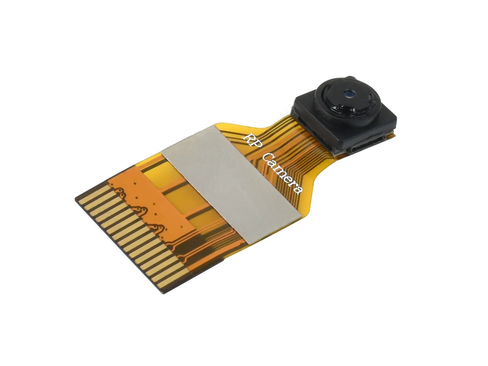
Camera and Sensor Modules
In a compact camera or sensor module, an assembled flex can connect a sensor positioned away from the main board with components or a mating interface on a supported end. The installed route must leave the component and solder-joint area supported, with the free span following the enclosure path. A useful check can confirm continuity and connector fit, then verify the specified power, communication, or sensor response in the intended operating condition. Optical performance and motion life, where required, need their own defined checks.
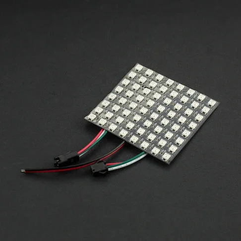
Displays and Wearable Electronics
A display flex can link a panel to its control board through a compact housing. The contact end needs to mate securely, while any local reinforcement supports insertion and keeps bending away from the connector. For a wearable layout, define whether the flex is formed once during installation or moves in use; repeated motion calls for a mechanical assessment suited to its route and travel. Functional verification can observe the specified display or control response when powered. The pictured flexible LED matrix illustrates a populated display surface; wearable builds also need the installed motion duty defined.

Industrial and Instrument Interconnects
In an instrument or control assembly, a flex can connect a front-panel interface, or boards on different planes. Its route must accommodate the fixed points, connector access, and service movement; support near the termination helps control strain at the joint. Where the flex mates with a socket on a separate rigid interface board, the board remains rigid and the flex is the interconnect. Checks can cover mating fit and continuity, followed by the specified powered input, output, or communication response. Environmental and service-movement requirements remain specific to the installed product.
FLJ can supply bare flex or rigid-flex boards, coordinate component sourcing, and assemble customer-supplied parts or components selected for the build. The resulting scope can cover single- or double-sided FPC assembly and the connector or termination work needed for the finished interconnect.
For a useful quotation, define the assembly quantity, board construction, component mix, and whether FLJ or your team will supply the parts. Include the connector and mating interface, any temporary carrier or permanent support, the flex areas that must remain free to bend, and the inspection or test you need. For component sourcing and alternatives, we work from the full part number and the approved build configuration. The quotation can then account for the selected board and components, setup and support, assembly, and agreed verification.