
MATERIAL SELECTION · CUSTOM FABRICATION
Halogen-Free PCB
Výroba
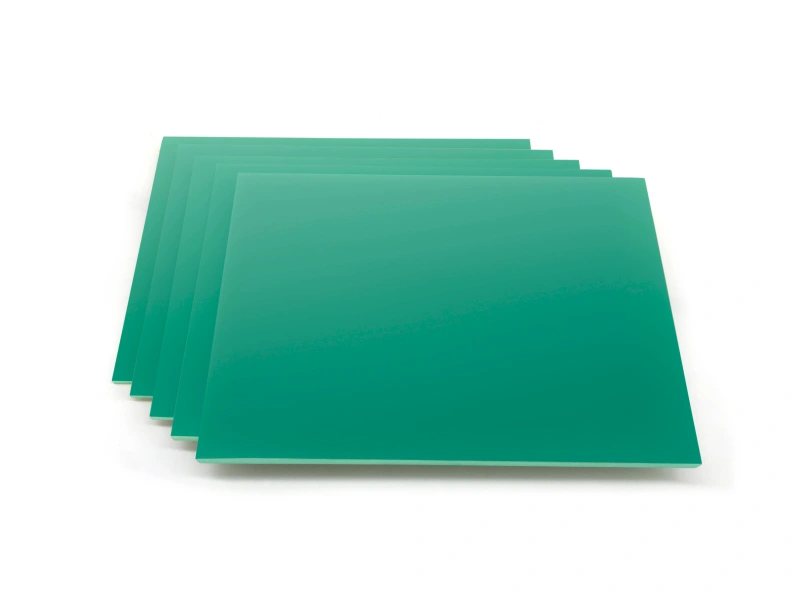
Material choices for your product’s halogen-free requirements.
FLJ manufactures halogen-free PCBs for prototypes and production, combining the selected laminate and prepreg with your copper layout, layer structure and finished-board features. From control circuits to demanding multilayers, material selection and fabrication work together to deliver the board your product needs.
Get a Halogen-Free PCB QuoteExplore material options ↓A DIFFERENT FLAME-RETARDANT SYSTEM
What changes
in a halogen-free PCB?
A halogen-free PCB starts with an insulating material specified for restricted bromine and chlorine content. In a glass-reinforced laminate, copper still carries the circuit and the glass fabric still provides reinforcement. The main change is in the resin and flame-retardant formulation.
Non-halogen flame-retardant systems replace the brominated chemistry used in many conventional laminates. Phosphorus-containing formulations are one approach. Their effect on thermal behavior, moisture uptake and electrical loss depends on the complete material system. Halogen-free therefore describes a composition requirement, not one universal performance grade.
For product teams, this creates a practical choice: meet a material policy while selecting the thermal and electrical behavior the circuit needs. A halogen-free construction can also be flame-retardant; its UL 94 classification is a separate property of the selected material.
MATCH THE MATERIAL TO THE CIRCUIT
Material options for your board
Start with the circuit’s duty. Thermal cycling and soldering exposure make resin stability and expansion important; longer signal paths make dielectric loss more significant. These needs can coexist with a halogen-free requirement.
| Material example | Selection focus | Typical Tg, DSC | Official information |
|---|---|---|---|
| ITEQ IT-170GRA1 | Mid-loss multilayers for industrial computing and communication electronics | 180°C | Data sheet — PDF |
| ITEQ IT-170GT | Mid-loss circuitry with thermal-reliability and expansion requirements | 185°C | Data sheet — PDF |
| Isola IS550H | High-power and high-voltage electronics with demanding thermal exposure | 200°C | Material data |
These are named material examples, not interchangeable substitutes. Tg describes the resin transition, not the finished board’s continuous operating temperature. The selected core, prepreg and copper construction define the material combination in the quotation.
Read the value.
Keep the condition.
At 10 GHz, ITEQ’s data sheets list Dk / Df of 3.8 / 0.009 for IT-170GRA1 at 50% resin content, and 3.9 / 0.0095 for IT-170GT at 55% resin content. Both use IPC-TM-650 2.5.5.13 for these measurements. Resin content belongs with the values: changing the glass-and-resin construction changes the dielectric, even within a named grade.
For a communication board, the mid-loss examples put signal behavior alongside the halogen-free requirement. For power electronics, IS550H offers a different balance centered on thermal reliability. The comparison starts with that duty, then the actual core and prepreg construction. Our FR-4 material overview explains the wider selection factors; the Isola range provides additional named material options.
FROM LAMINATE TO FINISHED CIRCUIT
Manufacturing with
the selected laminate
Forming and bonding the multilayer circuit
Inner copper layers are imaged, etched and inspected before pressing. Prepreg then fills the spaces around those copper features and cures to bond the stack. Resin quantity, flow and the press cycle determine whether the construction fills properly and reaches its intended dielectric spacing.
The cure cycle follows the selected resin system. For example, Isola describes IS550H as a higher-viscosity material than most halogenated FR-4 grades and recommends a corresponding lamination approach. FLJ sets heat rise, pressure and cure for the material and board construction, with moisture-controlled handling of the bonding sheets before layup.
Making the plated connections
Drilling exposes the inner copper layers at each interconnecting hole. Tool condition and chip removal influence the surface left behind. Hole-wall preparation removes resin residue from the connection surfaces, and copper deposition establishes the conductive path between layers.
FLJ matches hole-wall preparation to the resin and hole geometry. The aim is to expose the intended innerlayer copper and prepare the insulating wall for metallization. A clean, well-prepared interface supports the plated connection through later soldering and thermal exposure. The IS550H processing guide illustrates how drilling and desmear are specified for one material system.
Completing the board
Outer-layer imaging and plating establish the remaining conductors. Solder mask protects the selected circuit areas, the surface finish prepares exposed contacts for their intended connection, and profiling gives each board its final outline. FLJ supplies individual boards or assembly panels with the specified copper and finish.
Copper-pattern inspection and electrical testing check the fabricated circuit. Microsections examine internal features such as hole copper and bonded layers; impedance measurements assess the specified transmission-line construction. Material documentation and board inspection complement each other.
THREE TERMS. DIFFERENT SCOPES.
Halogen-free, RoHS
and lead-free
Halogen-free
Specified limits for bromine and chlorine in the declared material or product scope.
RoHS
Restrictions on listed substances in electrical and electronic equipment, including certain brominated flame retardants. It is not a blanket ban on all halogens.
Lead-free
Lead content in the relevant material or soldering system and the associated assembly process. It does not establish bromine or chlorine content.
From laminate
to the supplied board
A laminate declaration describes that laminate. A bare-board declaration also needs to account for the other materials included in its scope, such as solder mask and marking ink. For an assembled board, components and assembly materials extend that scope further. Keeping these levels clear gives purchasing and engineering teams a meaningful material statement.
MATERIAL CHOICES IN ELECTRONICS
Applications and custom PCB supply
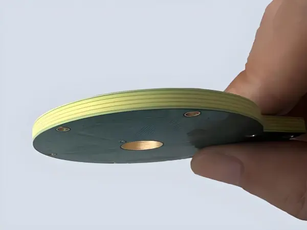
Control and power electronics
Industrial control boards combine signal processing, connectors and power circuitry. A halogen-free grade can meet the product’s material policy while thermal stability, insulation and copper construction serve the circuit itself. For higher-power or high-voltage electronics, grades such as IS550H place additional emphasis on thermal reliability.

Communication and computing hardware
Communication and computing boards bring a different selection focus: dielectric loss and the manufactured signal geometry. The ITEQ examples above show how a halogen-free requirement can be combined with a mid-loss material choice for routers, backplanes and computing hardware.
Photographs illustrate materials and hardware; appearance does not identify halogen content, laminate grade or a customer project.
PROTOTYPE TO FINISHED SUPPLY
Your material choice.
A board ready for the next build.
Žádost o cenovou nabídkuFLJ produces sample quantities and production batches using the selected construction. Bare boards can continue into Osazení desek plošných spojů, with component sourcing, placement and soldering included in the supplied build. Send the board files, quantity and material designation—or the thermal, electrical and halogen-free requirements—to request a quotation.