
PCB Electrical Testing
Check that the bare PCB connections match the intended circuit before assembly. FLJ reviews continuity, isolation, test data and the appropriate electrical test route with your board design.
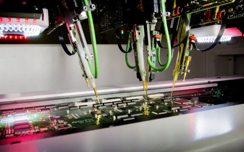
What does bare-board electrical testing check?
Bare PCB electrical testing checks conductive connections before components are fitted. Continuity checks look for broken connections within a net; isolation checks look for unintended connections between separate nets.
A board can look correct and still contain an electrical defect. Testing provides a different check from visual inspection because it compares electrical behavior at accessible points with the expected connectivity.
Bare-board testing does not demonstrate that an assembled product will boot, communicate or perform its application. Those checks belong to PCBA in-circuit or functional testing. Keeping the scopes separate helps you select the right verification at each production stage.
Flying probe and fixture-based approaches
The test route depends on the board geometry, accessible points, quantity and repeat-production plan.
A dedicated fixture brings tooling and setup considerations; flying probe reduces the need for a board-specific contact fixture but follows a programmed probing sequence. We review the practical route for your design rather than assigning it by quantity alone.
| Approach | How it works | When it is useful to discuss |
|---|---|---|
| Flying probe | Movable probes contact programmed points on the bare board | Prototypes, changing designs and lower-volume jobs |
| Dedicated test fixture | A purpose-built contact arrangement tests the specified board | Stable designs and recurring production quantities |
| Continuity checks | Checks the intended connections within each net | Open traces, broken vias and missing connections |
| Isolation checks | Checks that separate nets remain electrically isolated | Unintended copper bridges and shorts between nets |
How the design data becomes a test program
Electrical test preparation links the fabrication artwork with the intended connectivity. An independent CAD netlist, where available, helps compare the exported manufacturing data with the design source. IPC-D-356 is a common format for exchanging bare-board net information.
Gerber data describes the board layers and can also carry useful attributes. Ucamco’s Gerber guidance explains how layer images, attributes and job information support the fabrication handoff. We review the files supplied rather than asking every customer to export the same package.
Send your existing Gerber and drill files first. If an additional netlist or clarification would help the test review, our team will contact you. When an independent netlist is unavailable, we discuss the data preparation route and what the resulting check establishes.
Review test access and unusual circuit features
Dense boards, recessed contacts, very small pads and unusual surfaces can affect probe access. Features such as intentionally connected regions, embedded resistive structures or designated no-test areas need to be represented clearly in the test information.
Share any known special features with the fabrication drawing. We review them against the artwork and the selected test method so intentional circuit behavior is not mistaken for a defect.
Controlled-impedance measurements are a separate check from basic open/short testing. If your drawing specifies impedance, we discuss the target values, construction and measurement structures as part of the broader PCB verification plan.
Test conditions and order documentation
The test plan identifies the connectivity source, applicable continuity and isolation conditions, and any agreed exclusions. Where a customer specification names a test method or acceptance condition, send it with the files so we can review it during quotation.
For first articles or recurring production, tell us what electrical test documentation your receiving team needs. We can discuss the agreed report scope and its connection to the board part number, revision and production job.
A bare-board electrical test record confirms the agreed electrical checks. It should not be presented as proof of every mechanical dimension, material property or assembled-product function. Those requirements belong to their corresponding inspection or test stage.
Electrical test settings and useful records
Electrical tests answer whether the connections match the intended board. We help define the test settings and records around the design.
| Test item | What is defined | Project guidance |
|---|---|---|
| Test data | Intended nets and accessible points | Review Gerber/CAD and available netlist information together |
| Continuity | Resistance threshold and permitted path | Agree the limit appropriate to the construction and test program |
| Isolation | Test voltage, resistance threshold and duration | Set the test around the intended net separation and board specification |
| Probe access | Pad size, spacing and supported board geometry | Select the practical probe or fixture arrangement |
| Reports | Build identity, test method and agreed result record | Discuss records useful to your receiving and engineering teams |
Start with the files you already have
A design that is still in development can still be reviewed. Send the available artwork, board quantity and any particular reliability or receiving-inspection concern. We will explain the proposed test route and follow up on the details that affect it.
For a repeat build, identify the approved revision and any changes to the layout or netlist. This keeps the test program aligned with the board being manufactured and makes the quotation easier to compare with the previous order.
Frequently asked questions
Does electrical testing check whether my PCBA works?
Bare-board testing checks PCB connections before assembly. Product behavior needs an assembled-board functional test with an agreed procedure.
Do I need an IPC-D-356 file before asking for a quote?
No. Send the files you have. We will review them and explain whether an additional netlist would help with the electrical test preparation.
Can flying probe test a prototype?
Flying probe is a useful route to discuss for prototypes because it can work without a dedicated board-specific contact fixture. Access and design details still guide the program.
Is impedance included in an open/short test?
No. Continuity and isolation verify connectivity. Controlled impedance requires its own agreed measurement approach and acceptance range.
Let’s review your next build
Send your available board files, drawings or project questions. Our team will review the information and follow up with you about the next step.