
Electronics manufacturing and assembly
Electronics Manufacturing Services (EMS)
PCB assemblies, connected subassemblies and enclosed electronic units.
FLJ combines PCB fabrication, component sourcing and assembly with cable, mechanical and box build work. We manufacture your selected assembly, load the applicable firmware and carry out the checks defined for the board or product you need delivered.

Electronic Assemblies We Manufacture
FLJ supplies populated boards, wired or electromechanical subassemblies, and enclosed electronic units. Select the delivery level that fits your product: the supplied parts, assembly work and checks follow that scope.
| Supplied assembly | What we build | Interfaces and checks |
|---|---|---|
| Populated circuit board (PCBA) | A fabricated board assembled with the specified components by SMT, through-hole or a mixed route. | Component placement, soldered connections and the electrical or operating checks defined for the board. |
| Wired or electromechanical subassembly | A PCBA with its specified harness, mounting bracket or panel parts, ready for the next integration step. | Connector pairing and pin mapping, mounting position and the included wired interfaces. |
| Enclosed electronic unit | A PCBA, supports, internal parts, and cables installed in the selected housing with its panel interfaces. | Installed connections and specified powered functions through the assembled unit’s external interfaces. |
PCB Fabrication and Assembly Services
We manufacture the bare board, prepare its component kit and populate it as a connected build. Board construction and component mix shape the route from copper and layer connections to the joints that form the PCBA.
Board Fabrication and Component Supply
Our PCB fabrication forms the copper patterns, layer connections and outline of the bare board. For a conventional multilayer build, inner copper patterns are formed and inspected, then aligned and laminated before drilling and plating connect the required layers. Outer copper, solder mask, the selected surface finish and profiling complete the construction. The manufacturing sequence follows the chosen stack-up and any build-up stages.
Through component sourcing, we prepare the parts for that board’s assembly kit. The full manufacturer part number retains the relevant package and grade options; purchasing records and package labels connect received parts to the selected BOM. Delivery form affects how materials enter production. When an alternative is approved by customer engineering, the selected part and its affected assembly information are carried into the build.
SMT, Through-Hole and Mixed Assembly
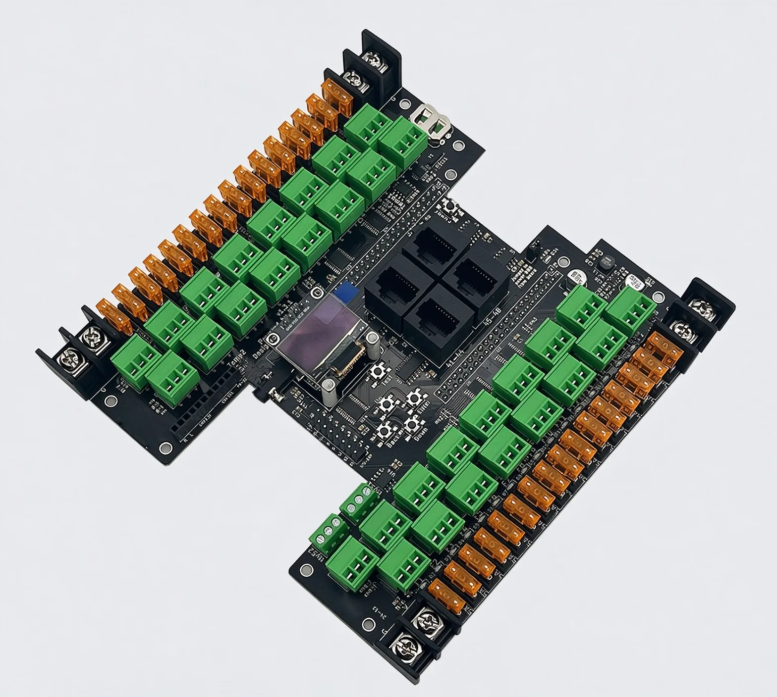
We print solder paste through the matched stencil onto the board pads, place the surface-mount components in their specified positions and orientations, and reflow the assembly to form the soldered connections. Stencil openings and paste release must suit the selected pads and packages. The thermal process accounts for the actual board and component arrangement: an oven setting alone does not describe the temperature reached at every joint.
Our through-hole and mixed assembly work adds leaded parts such as connectors or larger components where the design requires them. We insert and support the parts, keep their leads accessible, and solder them in a sequence suited to the component mix and existing joints. Placement, soldering and the selected connection checks form the supplied PCBA, whether it is an engineering sample or a repeat build.
Cable Assembly and Product Integration
Wired and Electromechanical Subassemblies
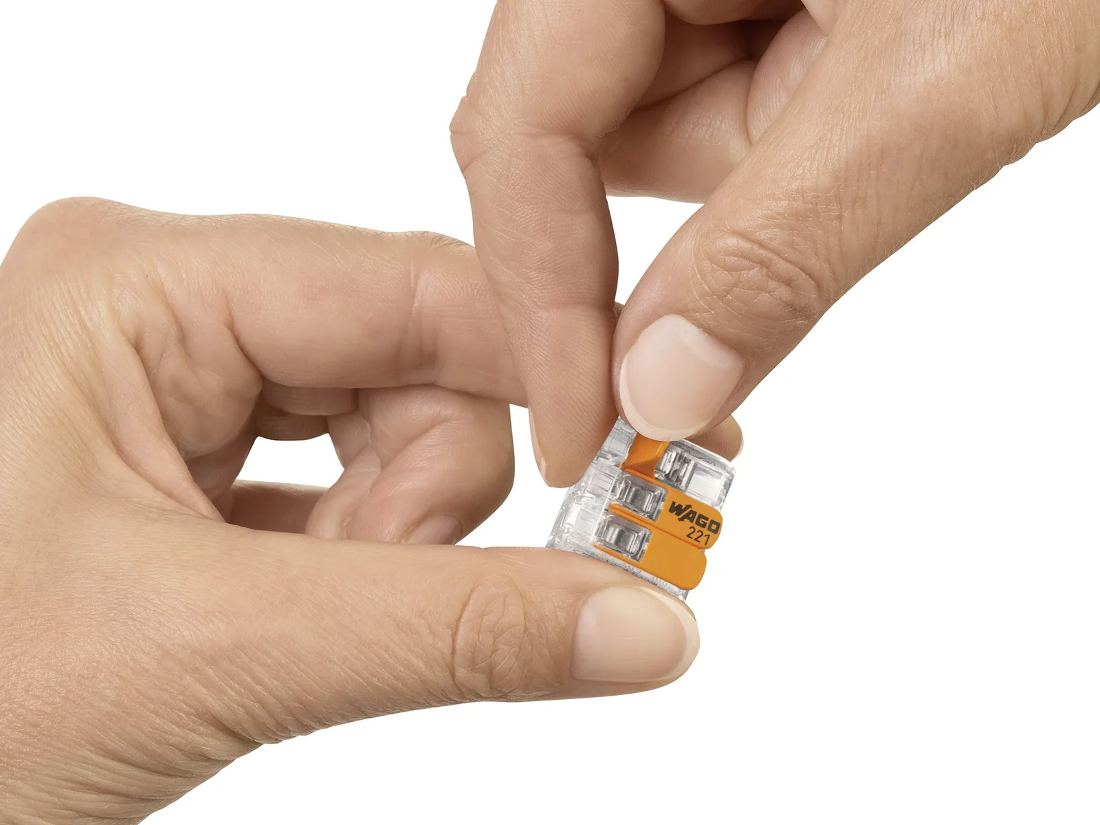
We build electromechanical subassemblies by combining the populated PCBA with its mating harness and mounting parts. Our cable and wire harness assembly work prepares the selected wire and end connections, seats terminals in their housings, and organizes the required branches, sleeves and position marks. Conductor termination forms the electrical path; insulation support and strain support handle different mechanical needs. The board connector, mating part and pin map remain matched as the assembly is connected and retained.
In an illustrative control module, a board connector links the PCBA to a panel interface. The pin map assigns the conductors; the specified physical keying controls mating orientation. The cable exit and branch position must also leave room for the bracket, fastening tool and programming connection. We preserve that installed route while assembling the harness and mounting parts, so electrical pairing and practical access are addressed together.
Box Build and Housing Assembly
In box build assembly, we install the PCBA, supports, internal parts, harnesses and panel connections in the specified enclosure. The assembly sequence keeps fastening and connection points accessible until the relevant work is complete. We route and support the wiring clear of cover joints and avoid transferring handling loads directly to its terminations.
We fit the specified fasteners and surrounding parts, check terminal seating and connector engagement, and inspect internal areas before the cover conceals them. Closing the housing completes the required physical arrangement, with the external interfaces and any required programming or test access available for the next operation.
Engineering Support for Prototype and Production
Manufacturing and Assembly Review
Our PCB assembly review matches the selected packages, land patterns, pin-one references and polarity to the intended placement and soldering route. Nearby parts may obstruct a soldering tool or hide a joint from inspection even when their bodies fit on the board. We identify those specific assembly conflicts for design correction and incorporate the released adjustment into production.
We also coordinate programming and test access with the populated assembly. A contact must be reachable, and the circuit must support the supply, reset or enable state needed for the intended operation. This connects physical access with the device-supported programming or measurement task.
Repeat Builds and Product Revisions
A change from a straight connector to an angled variant, for example, can alter the cable exit and tool access even if the pin assignments stay the same. The revised selection is checked against its mating part, bracket and cover. Where an electrical change also affects operation, the affected firmware and test instructions follow the hardware release. We carry the released part and installation references into the next build.
Observations from a first assembly refine the positioning, support and installation sequence used for repeat supply. FLJ keeps the applicable material and drawing revisions together with the relevant assembly and configuration references, so the next build reproduces the specified module and its connections.
Programming, Testing and Delivery
Firmware Loading and Product Configuration
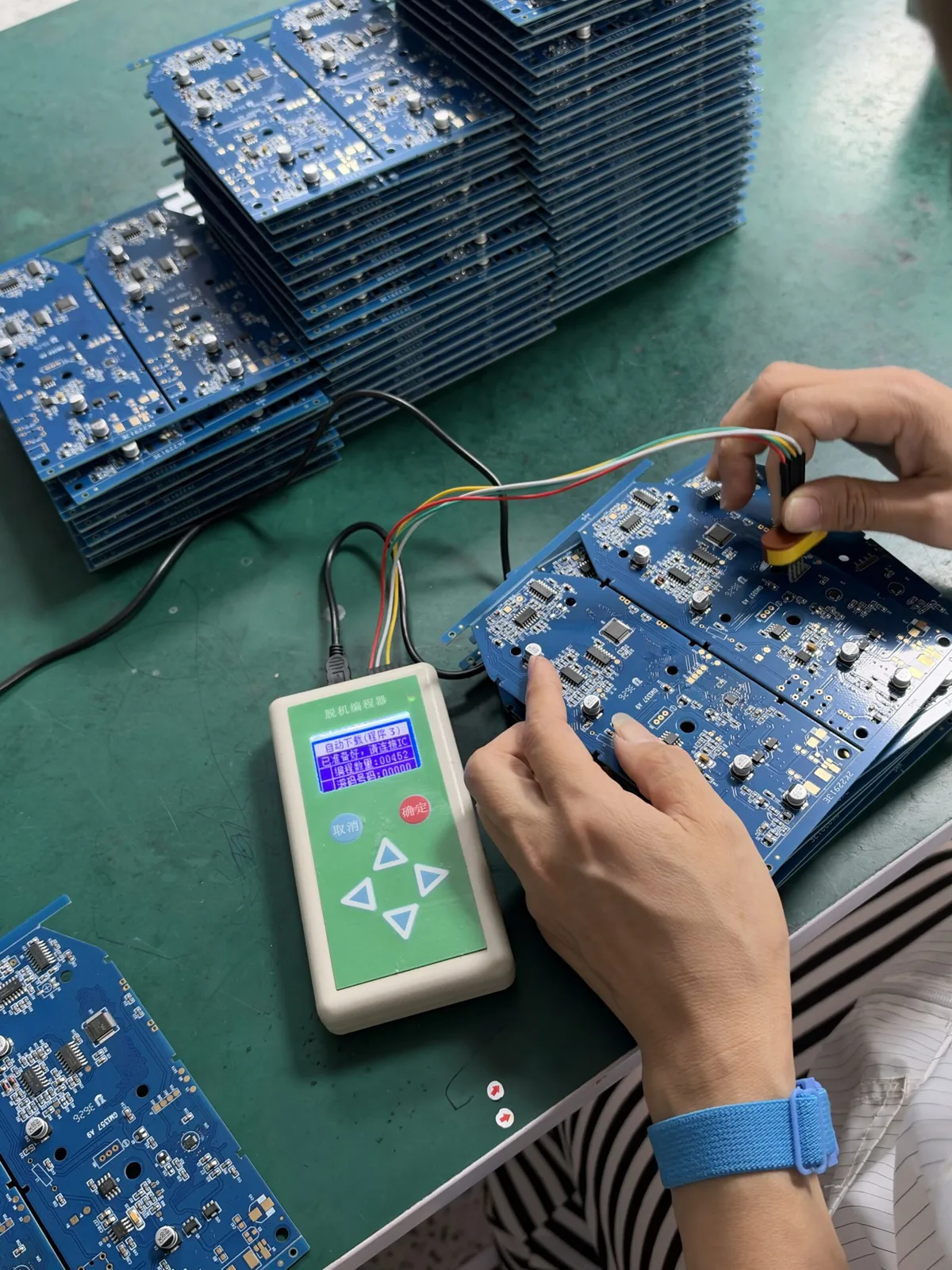
FLJ loads the released firmware or data through the route supported by the selected device. Our IC programming work can take place before assembly through a matching socket or adapter, or on the populated board through its accessible programming connection. Device support, supply, reset and protection conditions determine the usable route.
The specified settings, protection states and supplied unit fields follow the device’s programming sequence. We apply the supported verification method to the designated programmed regions and keep the image and configuration tied to the hardware build. The subsequent powered checks establish the board or product’s operating response.
Assembly and Interconnect Checks
FLJ inspects components and connections at stages that preserve access to the relevant features. Checks address orientation, connector and terminal seating, cable routing and support, and board or panel fit. In an enclosed build, the internal areas are inspected before the cover hides them; the supplied PCBA or subassembly has its own corresponding inspection scope.
The wiring reference defines the required harness endpoints. Continuity and open/short checks examine those electrical paths, while seating and mechanical support are checked as separate physical features. Optical inspection examines visible assembly features; where specified for connections hidden beneath a package, X-ray inspection addresses the obscured geometry.
Functional Checks for Boards and Units
Our functional testing applies the specified supply and configuration, introduces an input or command, and observes the response at the required point under the defined load and limits. A returned status and a measurement at the output terminal answer different questions. We use the required observation to check the product function.
A supplied PCBA can be checked at board level. For a completed unit, the test can include the added harness, panel connection and external interface in the assembled input-to-output path. The executed sequence and required results correspond to the delivered hardware and firmware configuration, with the specified test records prepared for that build.
We identify and pack the assembly for its specified delivered condition, including the required labels and accompanying items. Packing protects exposed connections and projecting parts during handling, with the product identification kept with the supplied assembly.

Share the board and assembly files, BOM and required delivery condition, together with the applicable enclosure, wiring, firmware and test requirements.