When PCB Materials Fail: The Cost of Ignoring IPC-4101
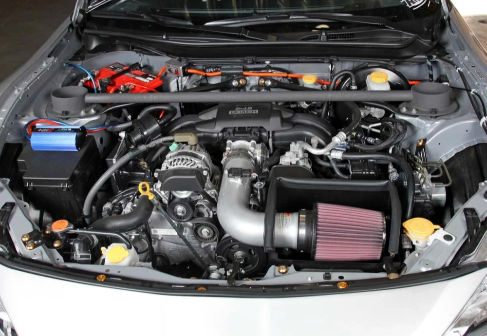
In 2019, a Tier-1 automotive supplier recalled 40,000 engine control units. The root cause was not a component defect. It was laminate delamination. The PCB material choice violated IPC-4101 requirements, and the failure happened after only 800 thermal cycles — far short of the 3,000 cycles required for under-hood applications.
The design team selected a standard FR-4 laminate with a Tg of 130°C. On paper, this seemed acceptable. But the engine compartment environment exposed the board to sustained temperatures above 125°C with spikes to 150°C. The resin system in that laminate was not formulated for high-temperature operation. IPC-4101 explicitly defines which slash sheets apply to high-thermal applications. This team used a general-purpose /21 material instead of a /126 or /129 high-Tg laminate.
What Happened Inside the Board
The failure mechanism was progressive. During thermal cycling, the resin expanded at a different rate than the copper and glass weave. With a low-Tg material operating near its glass transition temperature, the Z-axis expansion became uncontrolled. Each cycle stretched the resin further. After several hundred cycles, the bond between the resin and glass fibers broke down. Micro-cracks formed. Moisture entered. Then copper barrel cracks appeared in plated through-holes.
The delamination started at internal layer interfaces where resin-rich areas existed. X-ray inspection later showed separation across entire plane layers. The boards passed initial electrical test at the factory. But they failed in the field after 6–12 months of real thermal stress.
The Cost Breakdown
The recall cost exceeded $4 million. This included replacement parts, dealer labor, and logistics. But the bigger loss was the qualification delay with the automotive OEM. The supplier spent 18 months re-qualifying with the correct IPC-4101 /126 laminate. During that time, a competitor took the socket.
IPC-4101 slash sheets are not suggestions. They define material behavior under specific stress conditions. Choosing the wrong one means the laminate may survive prototyping and even pass initial reliability testing. But real-world thermal loads will expose the mismatch. The failure is predictable. Engineers who ignore the slash sheet classification system are not taking a calculated risk — they are guessing. And in automotive electronics, guessing costs millions.
What IPC-4101 Actually Specifies
At its core, IPC-4101 does not describe finished circuit boards. It specifies the base materials used to build them — the raw laminates and prepregs that fabricators receive from material suppliers before any etching, drilling, or plating begins. This distinction matters because a board’s long-term reliability is often decided before the first copper trace is imaged. If the base material cannot handle the thermal or electrical stress of the application, no amount of careful layout work will save it.
The standard is organized around a system of slash sheets. Each slash sheet — designated by a number after the main specification, like /99 or /126 — defines a complete material specification for a specific family of laminates. A single slash sheet covers the resin system, reinforcement type, glass transition temperature, decomposition temperature, and a full set of minimum property requirements. Engineers who work directly with slash sheet numbers are specifying an exact material profile rather than a generic “FR-4” or “high-Tg” callout on a fabrication drawing.
What the Property Tables Cover
Every slash sheet includes detailed property tables that establish both the test method and the minimum acceptable value. These tables cover electrical properties like dielectric constant and dissipation factor at multiple frequencies. They also specify mechanical properties including flexural strength, peel strength, and moisture absorption limits. Thermal properties receive equal treatment — time to delamination at 260°C, TMA glass transition, and Z-axis expansion are all listed with clear pass/fail thresholds.
The key point is that IPC-4101 does not describe how to process these materials. It only defines what the material must achieve to be considered compliant. This leaves fabricators with clear acceptance criteria while giving material suppliers room to innovate on formulation. A laminate that meets the /126 specification from one manufacturer is functionally interchangeable with another supplier’s /126 product — at least on paper. Production reality often introduces subtle differences in drilling behavior or resin flow, but the specification baseline remains the common reference point for incoming inspection and supplier qualification.
Slash Sheets Decoded: Matching Material to Application
| Slash Sheet | نوع مواد | Tg (°C) | Td (°C) | Key Characteristics | Typical Applications |
|---|---|---|---|---|---|
| /21 | Standard FR-4 (Dually Functional Epoxy) | 110–130 | ~310 | Low cost, basic performance | Consumer electronics, general-purpose PCB |
| /24 | High Tg FR-4 (Tetra-functional Epoxy) | ≥150 | ~320 | Improved thermal resistance | Industrial control, automotive electronics |
| /26 | Halogen-Free High Tg FR-4 | ≥170 | ≥340 | RoHS compliant, stable performance | Industrial and environmental-friendly designs |
| /98 | High Tg Multifunctional Epoxy | ≥150 | ~325 | Low signal loss, stable dielectric | High-speed digital PCBs |
| /99 | Enhanced High Tg Epoxy | ≥170 | ~340 | Excellent lead-free solder resistance | Industrial and communication equipment |
| /121 | Legacy FR-4 Standard | ~130 | ~310 | Traditional baseline material | Low-cost PCB applications |
| /124 | High Tg Epoxy (Unfilled) | ≥150 | ~325 | Good drillability and processing | General industrial boards |
| /126 | High Performance High Tg Epoxy (Filled) | ≥170 | ≥340 | High dimensional stability | Multilayer and HDI PCBs |
| /129 | Low CTE High Tg Epoxy | ≥170 | ≥340 | Low thermal expansion | High reliability electronics |
| /130 | High Layer Count Low CTE Material | ≥170 | ≥340 | Excellent warp resistance | Backplanes and high-speed systems |
Most engineers don’t read the full slash sheet. They scan the IPC-4101 designation, check two or three numbers, and move on. That works until the laminate behaves differently than expected in assembly or thermal cycling.
The slash sheet number is a shorthand, but it encodes real performance boundaries. A /126 sheet, for example, points to a high-Tg FR-4 with a glass transition temperature above 170°C. A /99 sheet specifies a low-CTE polyimide for applications that see repeated thermal shock. The difference isn’t academic. It shows up in plated through-hole reliability after 2,000 cycles.
Tg: The Starting Point, Not the Whole Story
Glass transition temperature gets the most attention during laminate selection. Higher Tg materials resist softening during lead-free soldering, so designers default to 170°C or 180°C grades. But Tg alone doesn’t predict field performance. A material with a 180°C Tg and a high Z-axis CTE above Tg will still crack barrels during thermal cycling. The resin softens less, but it still expands. That expansion, if unconstrained, creates strain.
I’ve seen boards built on 180°C Tg laminates fail before 150°C Tg boards because the CTE mismatch was worse. The slash sheet tells you both numbers if you know where to look.
CTE and the Z-Axis Problem
Z-axis CTE matters more than most designers assume. Below Tg, most FR-4 systems sit between 45–65 ppm/°C. Above Tg, that number jumps to 250–300 ppm/°C for standard materials. The IPC-4101 slash sheet defines maximums for each temperature range. A /124 sheet caps Z-axis CTE at 3.5% total expansion from 50°C to 260°C. That’s a tighter window than older /21 sheets, which allowed 4.5% or more.
When a board cycles between -40°C and 125°C, the Z-axis expansion and contraction work against the copper plating. Over time, barrel cracks initiate at the resin-reinforcement interface. Lower CTE materials slow this process. They don’t stop it, but they buy margin.
Matching the Slash Sheet to the Real Application
High-speed digital designs often default to low-Dk materials like those in the /70 family. But low dielectric constant doesn’t help if the board delaminates during rework. For dense multilayer boards with heavy copper, I prioritize thermal reliability over electrical performance. A /99 polyimide or /126 high-Tg FR-4 handles multiple thermal excursions better than a low-loss material with a lower decomposition temperature.
The slash sheet also defines peel strength, moisture absorption, and flammability rating. These matter less for bench prototypes. They matter a lot for boards heading into automotive or aerospace qualification. If the laminate absorbs 0.5% moisture instead of 0.2%, impedance shifts enough to cause bit errors at 25 Gbps. The slash sheet flags that before the first prototype is built.
Thermal Reliability: Why Tg Alone Isn’t Enough
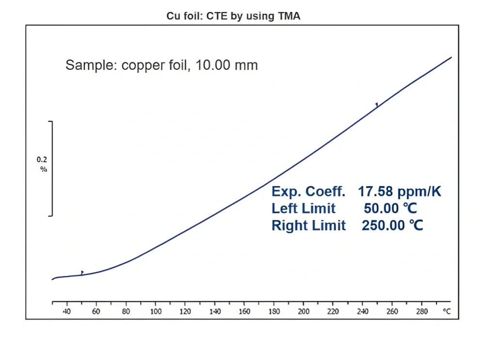
I’ve seen multilayer boards come out of rework with the Tg comfortably above the process temperature, yet the vias looked like craters on the inner layers. That’s when you learn the hard way that Tg is just the point where the resin softens. It says nothing about when the material actually starts to decompose.
Decomposition Temperature (Td)
Td is where the resin system begins to break down chemically, not just soften. You’ll typically see a 5% weight loss threshold defined by thermogravimetric analysis. A high-Tg material with a low Td is a trap. It survives lead-free soldering once, maybe twice, but the third thermal cycle during rework triggers irreversible damage. The bond between glass and resin weakens. You can’t see it from the outside, but the CAF resistance is already gone.
T260 and T288: Time to Failure
These are the numbers that tell you how long a laminate survives at temperature before delamination. T260 tests at 260°C, T288 at 288°C. In production, we watch boards on the wave solder pallet. A material with T260 under 10 minutes will start showing measling or blistering before the shift is over if there’s any stoppage. IPC-4101 slash sheets specify minimum T260 and T288 values for each material grade. Ignore them, and your rework yield drops off a cliff around the third panel.
Real Thermal Performance
Thermal reliability isn’t one number. It’s the interaction between Tg, Td, T260, T288, and moisture content. A laminate with 0.3% absorbed moisture hits the reflow oven and the water expands faster than the resin can outgas. The T260 might be 30 minutes on a dry coupon, but that same material fails in 3 minutes with moisture present. I’ve seen production lots pass IPC-TM-650 thermal stress on dry samples, then delaminate in assembly because the boards sat in a humid warehouse for two weeks. The slash sheet data assumes controlled conditions. The factory floor rarely provides them.
CAF Resistance: The Hidden Failure Mechanism
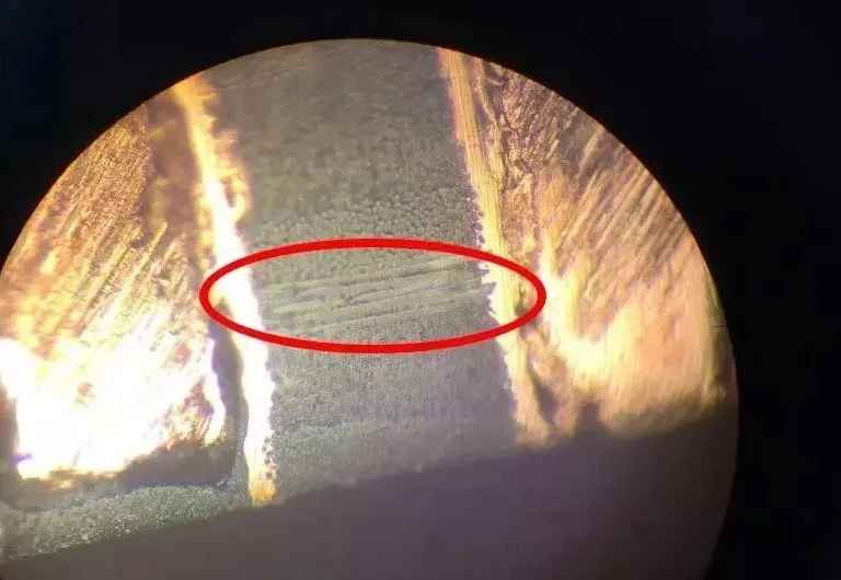
We once traced a field return back to a perfectly manufactured board. Every impedance value was within tolerance. Every cross-section passed. The failure was a short between a 3.3V plane and a ground via, deep inside the laminate. Under a microscope, we saw the telltale dark, dendritic filament growing along a glass fiber bundle. This was conductive anodic filament (CAF) formation—a failure that leaves zero trace on an electrical test at the factory.
CAF is electrochemical migration that happens inside the board, not on the surface. Copper ions dissolve from the anode, travel along the weakened resin-glass interface, and plate out at the cathode. Over months in humid service, a conductive path grows where none existed. The board works until it doesn’t. There is no gradual drift to warn you.
IPC-4101 addresses this through material qualification, not just process control. The standard defines specific CAF resistance test methods and performance criteria for base laminates. Slash sheets like /126 and /129 require coupons with closely spaced through-holes or vias, stressed under high humidity and DC bias for extended periods. The pass/fail line is clear: no filament growth exceeding a defined threshold after 1,000 hours.
The Glass Bundle Problem
Not all glass weaves are equal. CAF travels along the hollow cores of certain glass fibers, especially in low-resin-content areas. IPC-4101-compliant laminates use specially treated glass finishes or higher resin-to-glass ratios to block this path. The difference shows in production. A standard FR-4 laminate might pass thermal stress but fail CAF testing at 50°C/90% RH within 300 hours. A qualified laminate under the same conditions survives beyond 1,500 hours.
What Testing Doesn’t Tell You
The standard’s accelerated test conditions are harsh, but they still idealize the real world. Coupons are clean, etched precisely, and free of drill roughness. Real boards have micro-cracks from dull drill bits, incomplete desmear, and residual plating chemistries. Every one of these defects becomes a nucleation site for CAF. I have seen boards pass material qualification yet fail in the field because the fabricator pushed drill hit counts past the recommended limit. The laminate was fine. The process created the weakness.
This is the hidden gap. IPC-4101 qualifies the material. It does not qualify your fabricator’s drill maintenance schedule or their desmear line control. CAF resistance is always a combination of both.
Material Certifications and What They Really Mean
A Certificate of Conformance (C of C) is the most common document you will receive with a laminate shipment. It is also the most misunderstood. A C of C is not a test report. It is a legal statement that the material, based on the manufacturer’s quality system, should meet a specific IPC-4101 slash sheet. The supplier signs it. The lab may never have touched your specific batch. In a high-reliability workflow, treating a C of C as a technical data sheet is a mistake. It is a traceability promise, not a verification.
The Gap Between a C of C and a Test Report
A real test report contains actual numerical values from a sample pulled from the lot you are buying. It lists the measured Tg by DSC, the Dk at 10 GHz, and the peel strength after thermal stress. The difference matters in production. I have seen a C of C claim IPC-4101/126 compliance while the actual batch, when independently tested, showed a Tg 8°C lower than the minimum. The material still worked for a low-layer-count board. It would have failed in a 24-layer backplane during lead-free assembly. A C of C would not catch that. Only a lot-specific test report would.
Verifying Against IPC-4101 During a Supplier Audit
During a supplier audit, do not just check if the C of C file exists. Ask to trace one certificate to its raw data. Follow the paper trail from the shipped lot number back to the internal test records. Look at the date stamps. If the test date is weeks before the ship date, the material was sitting, and moisture uptake could shift Dk. Also, check how they handle borderline results. A good supplier quarantines the lot. A bad one ships it with a C of C and hopes you do not test it yourself. IPC-4101 sets the property limits. Your audit verifies the integrity of the system claiming to meet them.
How a PCB Manufacturer Ensures IPC-4101 Compliance
When a shipment of FR-4 laminate arrives at the loading dock, the first thing we check is not the paperwork. It is the label on the pallet against the physical sample cut from the edge of a sheet. I have seen entire lots where the C of C listed the correct IPC-4101 slash sheet, but the actual glass transition temperature measured 15°C lower than specified. That gap matters. A 130°C Tg material sold as 150°C will survive reflow. It will not survive two years of thermal cycling in an engine control unit. So incoming inspection starts with identity verification: manufacturer, date code, and slash sheet number matched to the purchase order. Then we cut a coupon.
Dielectric Constant and Loss Tangent Testing
The real engineering work happens at the test bench. IPC-4101 defines Dk and Df limits for every slash sheet, but the standard allows variation within a range. For high-speed digital boards, that range is too wide. We measure Dk and Df using a split-post dielectric resonator at 1 GHz and sometimes at 10 GHz if the application demands it. One batch of “high-speed” material from a qualified supplier showed Dk at 4.1 instead of the expected 3.8. That shift changed the impedance profile of every differential pair on the layer stack. The material technically passed IPC-4101. Functionally, it would have caused signal integrity failures. We rejected the lot.
Process Controls After Material Acceptance
Passing incoming inspection does not end the compliance story. The same laminate behaves differently depending on pressing parameters, heating ramp rates, and cooling profiles. A qualified PCB manufacturer must lock down these variables per material type. We maintain separate press cycles for standard FR-4, high-Tg, and halogen-free laminates. Mixing them is not acceptable. The resin flow characteristics differ, and a profile optimized for one slash sheet will under-cure or over-stress another. We track every press cycle against the material lot number. If a batch shows delamination after thermal stress testing, we can trace it back to either a material defect or a process deviation within minutes.
This is where many low-cost suppliers cut corners. They run one generic press cycle for everything and rely on the laminate supplier’s C of C as proof of compliance. That works until a field return lands on your desk. Real IPC-4101 compliance is not a document. It is a system of measurement, traceability, and process discipline that starts at the receiving dock and continues through every lamination cycle.
Specifying IPC-4101 in Your Fabrication Drawing
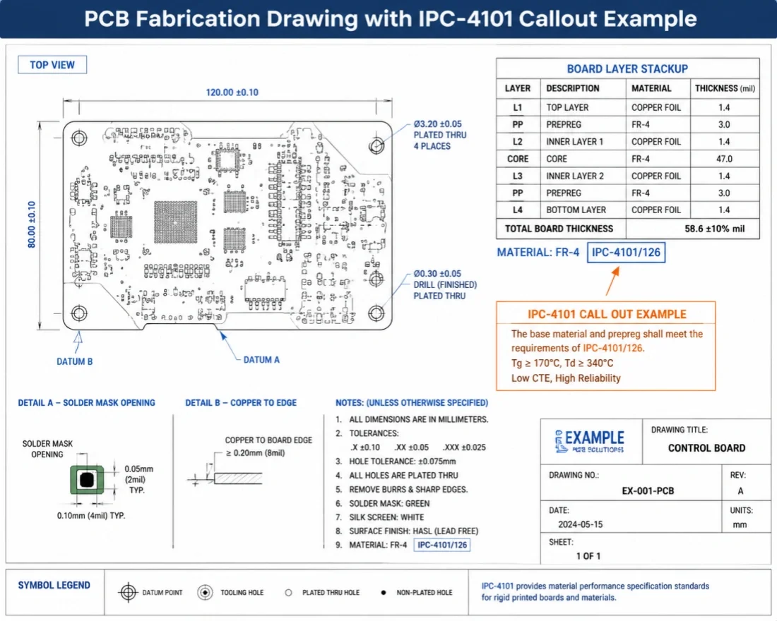
Most fabrication drawings I review still call out the standard incorrectly. The note usually reads something like “Material per IPC-4101” — and that is where the problem starts. IPC-4101 is not a material specification. It is a classification system with over 60 slash sheets. Each slash sheet defines a distinct laminate or prepreg type with its own resin system, reinforcement, glass transition temperature, and flammability rating. Calling out the base standard without the slash sheet tells the fabricator nothing useful.
What a Correct Callout Looks Like
The fab note must include three elements: the base standard, the specific slash sheet number, and any additional performance requirements not covered by the slash sheet. A proper callout reads:
This tells the fabricator exactly which material category to source. Slash sheet 126 defines a brominated epoxy woven E-glass laminate with a UL 94 V-0 rating. The added Tg requirement closes a gap — some /126 laminates can dip below 170°C depending on the supplier, so specifying 175°C minimum eliminates borderline materials.
Prepreg Notes Matter Too
Many designers forget that prepreg requires its own slash sheet callout. The laminate base and the prepreg used for bonding do not always share the same slash sheet. For a /126 laminate stack, the corresponding prepreg is typically /126 as well, but you should verify resin compatibility. The fab note should state:
You let the fabricator choose the specific prepreg style — 1080, 2116, 7628 — because that decision depends on their process capability and the layer-to-layer spacing you specify elsewhere in the stackup table. Do not over-specify the glass style unless you have a controlled impedance reason to do so.
What to Avoid in Fab Notes
Do not write “or equivalent” after the slash sheet number. That phrase creates a loophole. A fabricator under cost pressure will substitute a lower-Tg material that technically meets the slash sheet’s minimum requirements but performs worse in thermal cycling. If you need flexibility, list acceptable alternate slash sheets explicitly: “IPC-4101/126 or /129 acceptable.” /129 is the lead-free compatible variant with higher thermal reliability. That is a deliberate choice, not an open invitation.
Frequently Asked Questions About IPC-4101
Can I substitute one IPC-4101 slash sheet for another?
No, not without engineering review. The slash sheet number is not a suggestion. It defines the exact laminate construction, resin system, and cure chemistry. Swapping one for another changes how the board behaves in assembly and in the field.
I see this mistake most often with lead-free transitions. A design calls for IPC-4101/126 — a standard FR-4 rated for Pb-free soldering. Someone in procurement finds a cheaper /121 laminate and asks if it’s “close enough.” It isn’t. The /121 uses a dicy-cured epoxy with a lower Tg and a decomposition temperature that can’t handle multiple 260°C reflow peaks reliably. You risk delamination, barrel cracking, or CAF failures that show up months later in the field.
The only safe substitution path is when the fab note explicitly allows it. For example, a drawing might say “IPC-4101/126 or /129 acceptable.” That works because /129 is the high-Tg, phenolic-cured variant of the same base system. It has better thermal reliability, not worse. The engineer made a deliberate choice to accept a higher-performance alternative. That’s not the same as letting purchasing pick whatever is cheapest.
If you must substitute, check three things. First, match the Tg and Td minimums from the original slash sheet. Second, verify the resin system is compatible with your reliability testing. Third, confirm the dielectric properties don’t shift your impedance targets. Even a small Dk change between two FR-4 variants can push a differential pair out of spec on a long run.
When in doubt, don’t guess. Ask the fab to provide the full laminate datasheet and compare it against the original IPC-4101 callout line by line.
Get an Engineering Review of Your Material Stackup
We see too many designs where the material stackup was copied from a previous project without checking if the laminates are still available or compliant. A stackup that worked in 2021 might now use a discontinued prepreg or a laminate that no longer meets IPC-4101 slash sheet requirements for lead-free assembly temperatures. When you submit your stackup for an engineering review, our team cross-references each layer against current material availability and the relevant IPC-4101 specification. We check things like resin content percentage, glass style, and Dk tolerance at your operating frequency. Sometimes the fix is a simple material substitution that maintains the same electrical performance. Other times the original laminate choice forces a redesign because the supplier changed the formulation. Either way, you find out before the board goes into production, not after.
If you need a manufacturing review of your PCB material stackup, contact our engineering team for a DFM check and material compliance verification.