


航空宇宙用PCBの意味
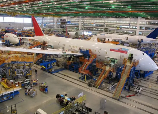
航空宇宙の電子部品には、クリティカルなものとそうでないものがある。例えば、航空機の自動操縦システムにはプリント基板(PCB)が使用されています。これらの基板は人々の安全を守るために非常に重要です。もし故障すれば、結果は非常に悪いものになります。.
対照的に、民間旅客機には座席制御用の回路基板がある。これらの基板は重要ではない。もし故障しても、人々が危険にさらされることはない。それでも、電子装置は “フェイルセーフ ”で火災を起こさないように作られなければならない。.
軍事用または航空宇宙用の電子機器を設計する際は、正しいルールに従うよう早めに計画を立てること。選択する部品と材料は、最終用途のニーズを満たすものでなければなりません。製品がミッションクリティカルな場合は、リードタイムが長くなることが予想されます。承認ステップにも時間がかかります。.
製造工程と素材の選択
PCBAの製造には、基板製造と組立という2つの主要な段階がある。重要な最初の選択は、どの基板材料を使用するかである。多くの場合、この選択には十分な注意が払われません。多くのPCB設計プログラムでは、デフォルトの誘電体としてFR4を使用しています。FR4は多くの用途に使用できます。.
FR4で十分な場合もある。そうでない場合もある。航空宇宙用PCBでは、ポリイミドのような代替材料の方が良い選択かもしれません。より良い材料の選択は、材料の特性と、その特性が基板製造にどのように影響するかを知ることから生まれます。宇宙システムは過酷な条件下で動作しなければなりません。そのため、材料の選択は非常に重要です。.
航空宇宙用PCBの主な材料要因
航空宇宙用プリント基板の材料を選ぶ際には、以下のポイントに注意してください:
-
強さ
宇宙での打ち上げや飛行では、強い振動や機械的ストレスが発生します。基板の強度は重要です。. -
耐久性
ほとんどの地上用PCBとは異なり、衛星用基板は打ち上げ後に修理や交換ができないことが多い。耐久性は非常に重要です。. -
熱抵抗
ボードは極端な暑さと寒さの下で動作し、機能し続けなければならない。これは、航空宇宙PCBAにとって最も重要なニーズの1つです。. -
安定性
空間の温度は非常に高くなったり低くなったりする。ボードはこのような極端な環境にも耐えられるものでなければなりません。. -
熱サイクル
システムは、高温から低温へ、そしてまた低温へという繰り返しのサイクルに対応しなければならない。. -
柔軟性
すべての航空宇宙用PCBが曲がらなければならないわけではありません。しかし、多くの設計では複数の基板とフレキシブルな相互接続が使用されている。例えば、キューブサットのような小型衛星があります。. -
耐薬品性
外部汚染と内部汚染は電子分野に害を及ぼす。宇宙放射線が主な心配事だ。しかし、他の汚染物質、特に湿気が現れることもある。これを避けるため、メーカーはハウジングを窒素でパージして密閉することが多い。また、コンフォーマルコーティングを使用することもある。.
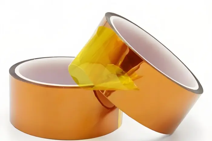
航空宇宙用基板として最も一般的な2つの材料は、FR4とポリイミドである。FR4は多くのPCBに適しています。ポリイミドは柔軟性と熱特性に優れています。そのため、用途によっては最適となる。上記のポイントから、これらの選択肢を見てみましょう。.
航空宇宙用基板におけるポリイミドとFR4の比較
航空宇宙用基板の製造は、多くの規則や規格に従わなければならない。航空宇宙用基板は、リジッド基板用のIPC-6012Dや、リジッド基板用のIPC-6012Dなどの特別な付録や仕様を満たす必要があります。 IPC-6013D フレックスおよびリジッド・フレックス・ボード用。ポリイミドと一部のFR4タイプは航空宇宙規則を満たすことができます。そのため、用途に応じて詳細を確認する必要があります。下の表は、材料を選ぶ際にチェックすべき点を列挙したものです。.
注:多くの表の「FR4」項目は、基本的なFR4を意味する。他のFR4グレードは航空宇宙用途に適した特性を示す場合があります。.
ポリイミドとFR4は、航空宇宙用PCBにとって重要な点で異なる。明確な違いの一つは柔軟性である。ポリイミドはフレックスおよびリジッドフレックス基板に使用される柔軟な材料です。FR4はリジッド基板用である。それでも、ポリイミドは基本的なFR4よりも強いことが多い。そのため、ポリイミドの方が耐久性に優れている。極端な温度や熱サイクルを想定するのであれば、ポリイミドが最適です。どちらの材料も汚染によく耐える。.
正しい選択はケースによる。ポリイミドが最適なシステムもある。また、宇宙船内部の熱制御で環境を安定させられる場合もある。その場合はFR4で十分かもしれない。基板設計も決定を左右する。フレックス基板には、大きく異なる設計ルールがある。例えば
-
ベンド部のビアは避ける。.
-
長寿命化のため、長い弧を描くようにトレースを配置する。.
-
曲げやすくするため、クロスオーバーには45~60度の銅フィレットを使う。(メーカーによっては異なる角度を使うこともある)。
-
レイヤーの数と曲げ半径を比較してください。.
-
銅のクラックを減らすために、他の設計ステップを使う。.
異なる業界の設計者は、材料選択プロセスを適応させなければならない。航空宇宙の場合、このステップはより重要です。極限状態を想定して計画を立てなければなりません。.
PCB製造に適用される航空宇宙産業規格
航空宇宙PCB規格の完全ガイドは長いです。以下は知っておくべき主な規格です:
-
ISO 9100 - 品質マネジメントシステムの基本規格。他の多くの規格はISOの考え方から来ている。顧客ニーズ、トップマネジメント、QMSプロセス、継続的改善に焦点を当てている。.
-
AMS2750E - 熱処理装置の高温ニーズをカバー。これには、熱処理プロセス用のセンサー、機器、テストが含まれます。.
-
AS478N - 航空宇宙部品にどのようなマークを使用し、どこにマークを配置するかを示します。.
-
AS5553A - 航空宇宙プラットフォームで使用される部品のサプライチェーンのルールを定める。.
-
AS9006A - 宇宙船システムの一部となりうるソフトウェアおよびソフトウェア・サポートに関する規則を定める。.
-
AS9100D - 航空宇宙サプライヤーのためのQMSのニーズを設定します。社内および外注の製造工程をカバー。顧客ニーズを強調。.
-
AS9101E - QMSの審査と結果の報告方法を示します。.
-
AS9102B - 第一条検査(FAI)のベースラインの必要性を列挙する。.
これらの航空宇宙規格は、エレクトロニクスやPCBに影響を与える分野をカバーしています。また、製品やサプライチェーンに適用されるその他の規則にも従う必要があります。.
PCBの実効熱伝導率が航空宇宙分野で重要な理由
熱制御は航空宇宙PCBAにとって重要な問題である。熱の広がりはすべての基板にとって重要です。宇宙空間では、空気で熱を移動させるのは難しい。真空のため、空気による熱移動は不可能です。宇宙で熱損傷を受けた基板を修理することはできません。だからリスクは高い。過熱によってボードが故障し、宇宙船全体が動かなくなることもあります。基板の設計には、PCBから熱を逃がす方法を盛り込む必要があります。.
PCBの実効熱伝導率とは何ですか?
PCBの実効熱伝導率とは、余分な熱を拡散し除去するボードの能力のことです。これにより、どのエリアも熱くなりすぎません。部品や材料が熱くなりすぎると、早期に故障する可能性があります。.
熱伝導率が低すぎるとどうなるのか?
実効熱伝導率が低いと、大きな問題を引き起こす可能性がある:
-
構造劣化
基板の温度が材料の限界値を超えると、基板が変形したり壊れたりすることがある。熱が逃げないと、高出力部品の近くにホットスポットができます。. -
コンポーネントの損傷
各部品には最高温度が設定されている。それを超えると、部品が機能しなくなったり、物理的な損傷を受けたりします。. -
デラミネーション
多層ボードの場合、ラミネーションは層を1つの構造にプレスする。材料の選択によっては、展開後に高温で層が破壊されることもある。. -
火災
極端な熱が長く続くと、部品や基板が発火することがある。過熱した絶縁体がアーク放電し、火災が発生する可能性があります。これは大惨事となる。基板や近くの部品が破壊される可能性があります。.
このようなリスクがあるため、メーカーは航空宇宙用基板の熱伝導率を確保する必要がある。.
最高の熱性能を実現する航空宇宙PCBAの作り方
地上システムと比べて、宇宙船のシステムは熱を室外に排出することができません。宇宙船の電子機器は、熱をシステム内部か、熱制御システム(TCS)によって設計された領域に移動させなければならない。TCSは宇宙船の設計の一部です。TCSを助けるために、PCBAは余分な熱を取り除かなければなりません。それをうまく行うために、以下のガイドを使用してください。.
PCBの実効導電率に関する熱設計ガイドライン
-
を知る 温度限界 ターゲット環境にあるボードの.
-
を満たす部品を使用すること。 航空宇宙製造規格.
-
適合するボード素材を選ぶ 宇宙環境のニーズ.
-
を実行する。 熱分析 設計上。これはボードが熱を逃がすことができることを証明している。.
-
必要に応じて特殊な部品や材料を使用する。例えば、MMICやセラミックは標準部品よりも高温に耐えることが多い。.
-
高い放熱性能が必要な基板については、上記の手順に従ってください。.
これらのステップは、ボードの熱を逃がす能力を最適化するのに役立つ。.
まとめとPhilifastについてのメモ
スペースエレクトロニクスは、耐久性と信頼性に関して、より高いルールを満たさなければなりません。このため、その設計と製造は、一般的なプリント基板とは異なります。このような品質ニーズは、委託製造業者(CM)との作業に影響する規則や基準に現れます。CMは初日から設計の一部であるべきです。彼らは、基板、部品、およびすべてのプロセスが航空宇宙規格に適合しているか、またはそれを上回っていることを確認する必要があります。.
Philifastは航空宇宙用PCBの設計と製造のお手伝いをいたします。弊社は厳格な基準で作業を行っています。適切な材料の選択、熱研究の実施、必要な品質チェックをお手伝いします。航空宇宙用PCBの設計、試作、製造のお手伝いが必要な場合、Philifastは設計から納品までサポートいたします。.
航空宇宙PCBプロジェクト用簡易チェックリスト
-
製品がミッションクリティカルな場合は、承認にかかる時間を長くする。.
-
必要な強度と熱特性を備えた素材を選ぶ。.
-
リジッド・フレックスまたはフレックス・ボードのフレックス・ゾーンは慎重に設計してください。.
-
熱分析を早めに行う。.
-
航空宇宙用途のIPCおよびAS規格に準拠。.
-
必要に応じて、コンフォーマルコーティングとエンクロージャーパージを使用する。.
お望みなら、, フィリファスト は、あなたの設計をレビューし、航空宇宙用にボードを準備するためのフィードバックを提供することができます。.