Ground traces and ground planes have impedance. When current flows through a ground path, a voltage will appear on that path. This voltage is noise. Noise voltage is one of the interference sources that can hurt system stability. Therefore, to lower ground noise we must first lower the ground impedance.
As everyone knows, the ground is the return path for current. For any signal, the signal must find a path back to ground that has the lowest impedance. So how we handle that return path is very important.
1 — Why return path size and shape matter
First, from the formula for radiation we know that the radiation strength is proportional to the loop area. This means the longer the return path and the larger the loop it makes, the more it will radiate and disturb other circuits. So when you lay out a PCB, you should try to make the power and signal return loops as small as possible.
Second, for a high-speed signal, giving it a good return path helps keep its signal quality. This is because the characteristic impedance of a transmission line on the PCB is usually calculated with respect to a ground plane (or a power plane). If there is a continuous ground plane near the high-speed trace, the trace’s impedance will stay constant. If a section of the trace has no nearby ground reference, the impedance will change. This impedance discontinuity will hurt signal integrity. Therefore, when routing, place high-speed traces on layers close to a ground plane. Or run one or two ground traces in parallel next to the high-speed trace. These ground traces work like a shield and provide a nearby return path.
Third, avoid routing signals across split power planes when possible. This is because when a signal crosses different power or ground splits, its return path becomes long and can pick up interference. That said, for low-speed signals crossing splits is not strictly forbidden because the interference they cause can be small. For high-speed signals you must be careful and avoid crossing splits when you can. You can also try to change the routing of the power planes to help.
Many electromagnetic interference problems come from ground design. Ground potential is the reference for the whole circuit. If ground is not stable, the circuit can fail. The goal of ground design is to keep ground potential as stable as possible and so remove interference.
Signal grounding methods usually fall into four types: floating ground, single-point ground, multi-point ground, and mixed ground.
2 — Grounding types
A. Floating ground
Purpose: Keep the circuit or the device isolated from common conductors that can cause ground loops. Floating ground also makes it easier to pair circuits that have different potentials.
Drawback: It can easily accumulate static charge and cause strong electrostatic discharge (ESD).
Compromise: Add discharge resistors to bleed off charge.
B. Single-point ground
Single-point ground means every circuit’s ground connects to the common ground at the same point. This can be split into series single-point and parallel single-point. Do not use single-point ground in systems where high-power and low-power circuits mix. The ground currents from the high-power part will affect the low-power parts. Also, the most sensitive circuit should be placed at the common point, because that point has the most stable potential.
The biggest advantage of single-point ground is there are no ground loops, so the design is relatively simple. But ground leads can be long and ground impedance can be large.
Single-point ground can be done two ways:
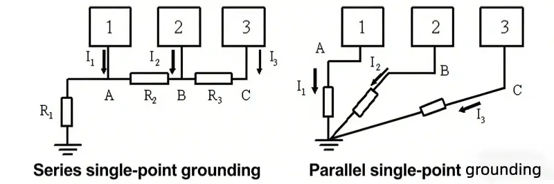
- Series single-point ground — This is simple. But because there is a shared ground conductor, a common ground impedance will exist. If the circuits in series have very different power levels, they will strongly interfere with each other.
- Parallel single-point ground — Each circuit runs a ground wire back to the common point separately. This avoids coupling on the common ground. But it needs many ground wires and is not practical in many cases.
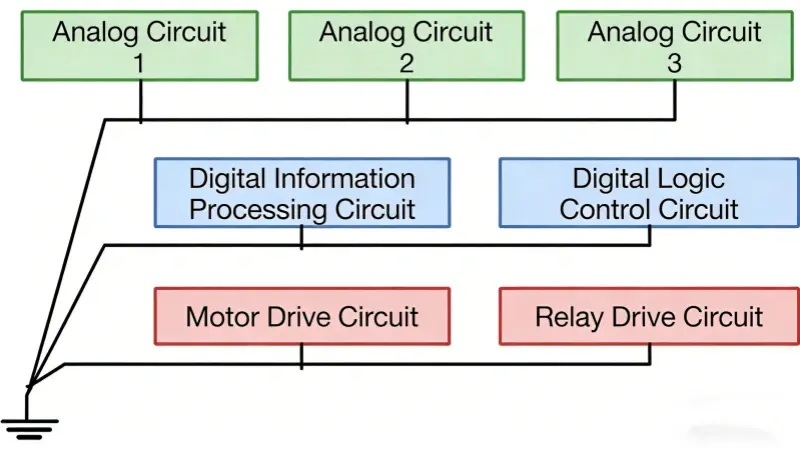
In real designs, you can use a mixed single-point approach that uses both series and parallel. Put circuits that do not interfere with each other on the same layer. Put circuits that easily interfere on different layers. Then connect the ground layers in parallel at the common point. (The original text referenced a figure here.)
Use: Single-point grounding is suitable for low operating frequencies (< 1 MHz).
Drawback: Not good for high-frequency situations.
Single-point ground is not suitable for high-frequency circuits because ground leads are long and the impedance from those leads becomes unavoidable. For high frequency, consider multi-point grounding.
C. Multi-point ground
Use multi-point grounding for high operating frequencies (> 30 MHz). In a multi-point scheme you replace individual ground return loops with one ground plane that each part of the circuit can use. The inductive reactance of a ground lead grows with frequency and with lead length. At high frequency, common ground impedance increases. So you must keep ground lead length as short as possible.
When using multi-point ground, try to find the nearest low-impedance ground surface to tie to. High-frequency digital circuits need parallel grounding. A simple way to do this is to use ground vias. When circuits run at high frequency, imagine a high-frequency signal moving along a ground trace and affecting nearby circuits. This can be very bad. So all circuits must return to ground nearby. Ground traces must be short. That is why multi-point ground exists.
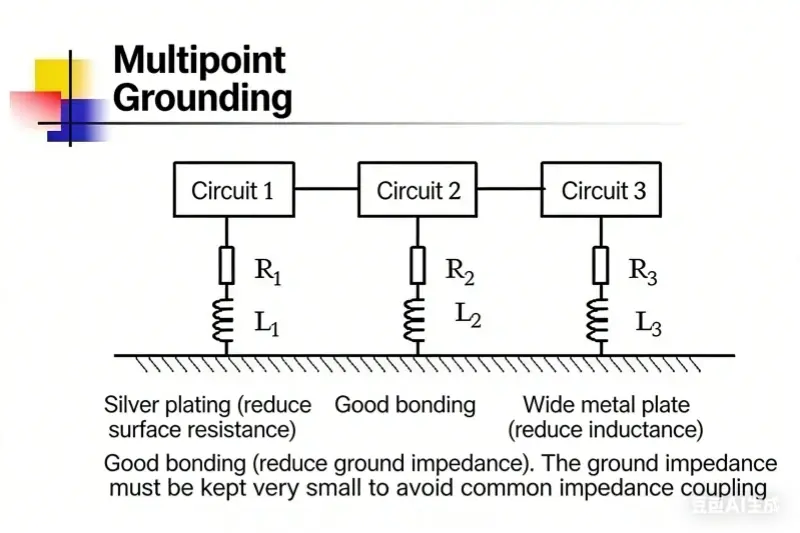
The goal of multi-point ground is to lower ground impedance. To lower impedance in a high-frequency circuit, consider two things: lower the ground resistance and lower the ground inductance.
Methods:
- Lower conductor resistance. From the relation between resistance and cross-sectional area we know that increasing the conductor area lowers DC resistance. But at high frequency the skin effect causes current to flow near the surface of conductors, so simply increasing cross section has limited effect. You can consider plating the conductor with silver because silver has better conductivity than many other metals and can reduce conductor resistance.
- Lower inductance. The best way is to increase the ground area. In practice, short ground leads and large ground area give better anti-interference performance.
At this point, some may ask what counts as a high-frequency circuit. According to Professor Yang Jishen’s book Electromagnetic Compatibility (EMC) Technology, usually circuits below 1 MHz are low frequency and can use single-point ground. Circuits above 10 MHz are high frequency and should use multi-point ground. If the longest ground lead is less than 1/20 of the wavelength at 1 MHz or 10 MHz, single-point grounding can still work. Otherwise use multi-point grounding.
D. Mixed ground
If the circuit has both high- and low-frequency signals, mixed grounding is a good choice. (The original text referenced another figure here.)
Look at the figure and the two structures shown. For the first structure assume it works mostly in a low-frequency environment. From the capacitive reactance formula Zc=12πfCZ_c = \frac{1}{2\pi f C}Zc=2πfC1 we know that at low frequency the capacitive reactance is large, while at high frequency it is small. So in this wiring the ground link is open at low frequency and nearly closed at high frequency. This wiring can avoid ground loop interference.
For the second structure assume it works mostly in high-frequency environment. From the inductive reactance formula ZL=2πfLZ_L = 2\pi f LZL=2πfL we know that inductive reactance is small at low frequency and large at high frequency. So in this wiring the ground link behaves like a conductor at low frequency and is open at high frequency. This wiring can avoid ground loop currents.
3 — Ways to connect different grounds
If you do not choose to use a whole plane as common ground, and a module has two ground nets, you must split the ground plane. That often interacts with the power plane. The ways to connect grounds are:
- Ordinary trace between grounds. This gives a reliable low-impedance connection for mid and low frequency signals.
- High resistor between grounds. A large resistor will allow a tiny leakage current if a voltage appears across it. This will slowly bleed charge until the potential difference becomes zero. Use this to tie floating grounds down gently.
- Capacitor between grounds. A capacitor blocks DC but passes AC. Use this in floating ground systems to pass high-frequency noise while blocking DC.
- Ferrite bead (magnetic bead) between grounds. A ferrite bead acts like a frequency-dependent resistor. It looks resistive for high frequencies. Use it for weak signal grounds with small fast current spikes.
- Inductor between grounds. An inductor resists rapid change. It can smooth peaks and fill valleys. Use it between grounds that have large current swings.
- Small resistor between grounds. A small resistor adds damping to slow down rapid ground current changes. When current changes rapidly this resistor makes the rising edge less steep.
All these choices give ways to control how noise transfers between grounds.
4 — Analog ground and digital ground
Analog and digital signals both need a return to ground. Digital signals change fast. They make a lot of noise on the digital ground. Analog signals need a clean ground reference to work well. If analog and digital grounds mix, the noise from digital ground will affect analog signals.
In general, separate analog and digital grounds. Then connect them with a thin trace or at a single point. The main idea is to stop digital ground noise from getting into analog ground.
5 — Star ground
The theory behind star grounding is that there is one point in the circuit that serves as the reference for all voltages. This is the star point. You can picture it: many wires run from one common point in a radial pattern like the rays of a star. The star point may not look like a star on the board. It may be a point on the ground plane. A key feature of a star ground system is that all voltages are measured relative to the same point on the ground network, not some uncertain “earth” reference.
6 — How to ground shields
The shield of a shielded cable and the cable drain wire should be tied to the board interface ground, not to the signal ground. This is because the signal ground often carries many noise voltages. If the shield ties to the noisy signal ground, the noise voltage will drive common-mode current on the shield and cause external interference. Poor cable design and poor shield grounding are often the largest source of EMI.
概要
In practice, choose the grounding method that fits the operating environment. A good choice can avoid interference and give the best circuit performance.
- Keep return loops small to reduce radiation.
- Keep high-speed traces next to continuous ground planes for stable impedance.
- Avoid crossing power plane splits where possible.
- For low-frequency systems (< 1 MHz) single-point ground often works.
- For high-frequency systems (> 10 MHz) use multi-point ground and short ground paths with lots of return area.
- For mixed systems use a hybrid approach with capacitors, inductors, resistors, ferrite beads, or small traces to control coupling.
- Separate analog and digital grounds and join them carefully.
- Tie cable shields to the connector ground or chassis ground, not to noisy signal ground.
These steps will help lower ground impedance and reduce ground noise, so the system will be more stable and reliable.