
Inside our
PCB & PCBA factory.
See the production resources, inspection methods and people that connect your design with a finished electronic assembly.
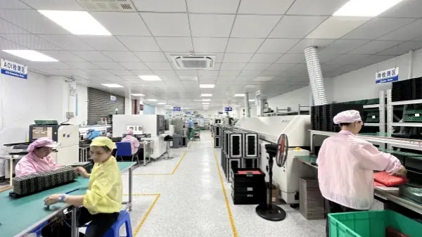
FLJ PCB brings PCB fabrication, SMT and through-hole assembly, component sourcing, programming and testing into a coordinated manufacturing service. Our assembly resources include seven SMT lines, two DIP lines and two manual soldering lines.
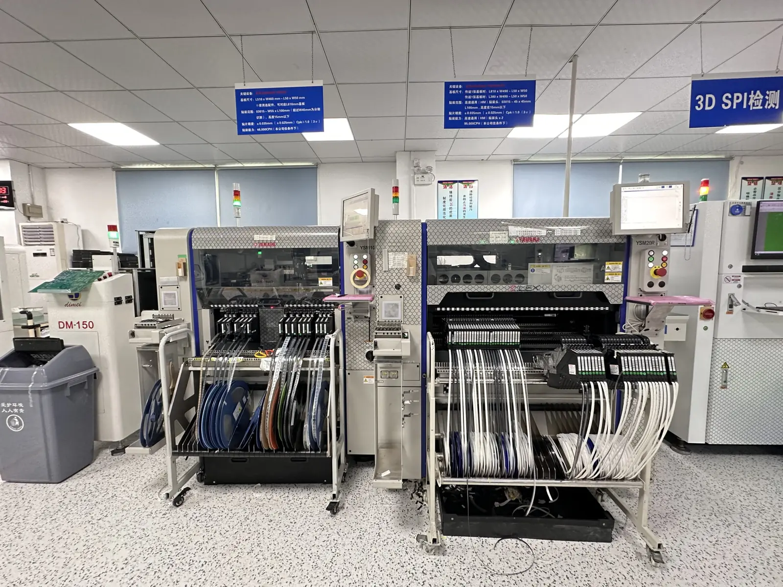
Manufacturing resources.
A connected build process.
Equipment matters when it is connected to the right files, materials and process settings. Our engineering, procurement, production and quality teams coordinate those inputs throughout the build.
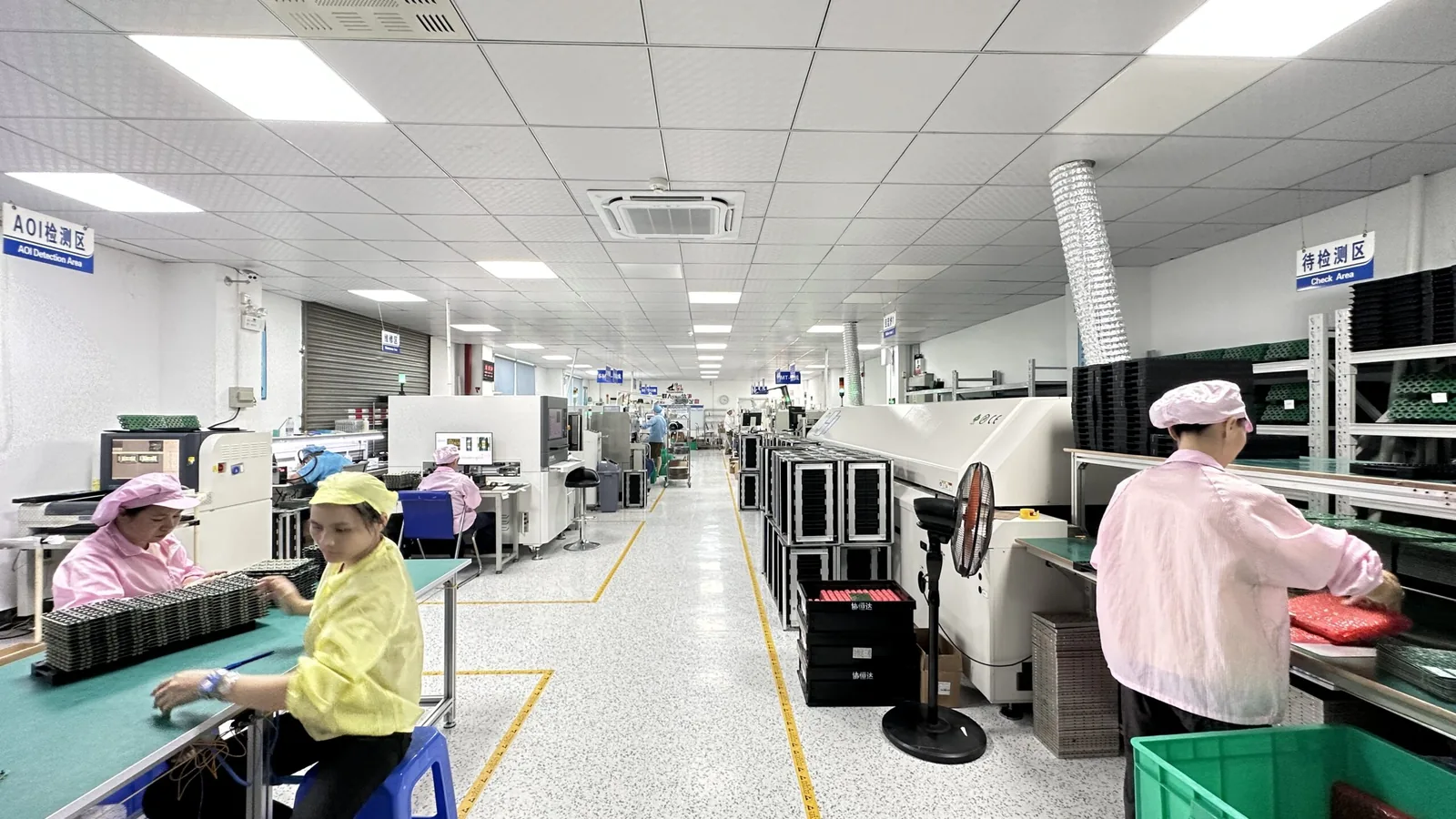
The board beneath the assembly
Manufacturing review starts with the Gerber data, drill files, stack-up, materials and finished-board requirements. Our PCB scope includes FR4 multilayer boards, HDI, flex, rigid-flex, RF, metal-core and ceramic constructions.
PCB manufacturing →SMT, through-hole & mixed builds
Surface-mount placement is supported by solder-paste printing, reflow and inspection. DIP, wave soldering and manual soldering resources support through-hole components and assemblies that combine both technologies.
PCB assembly →More than placing components
IC programming, functional testing, cable work and final product assembly can be included in the project. Confirm firmware, interfaces, fixtures and acceptance requirements before releasing the manufacturing package.
Electronics manufacturing services →More from the production floor.
A closer look at our assembly environment, production workstations, component preparation and the people behind the build.
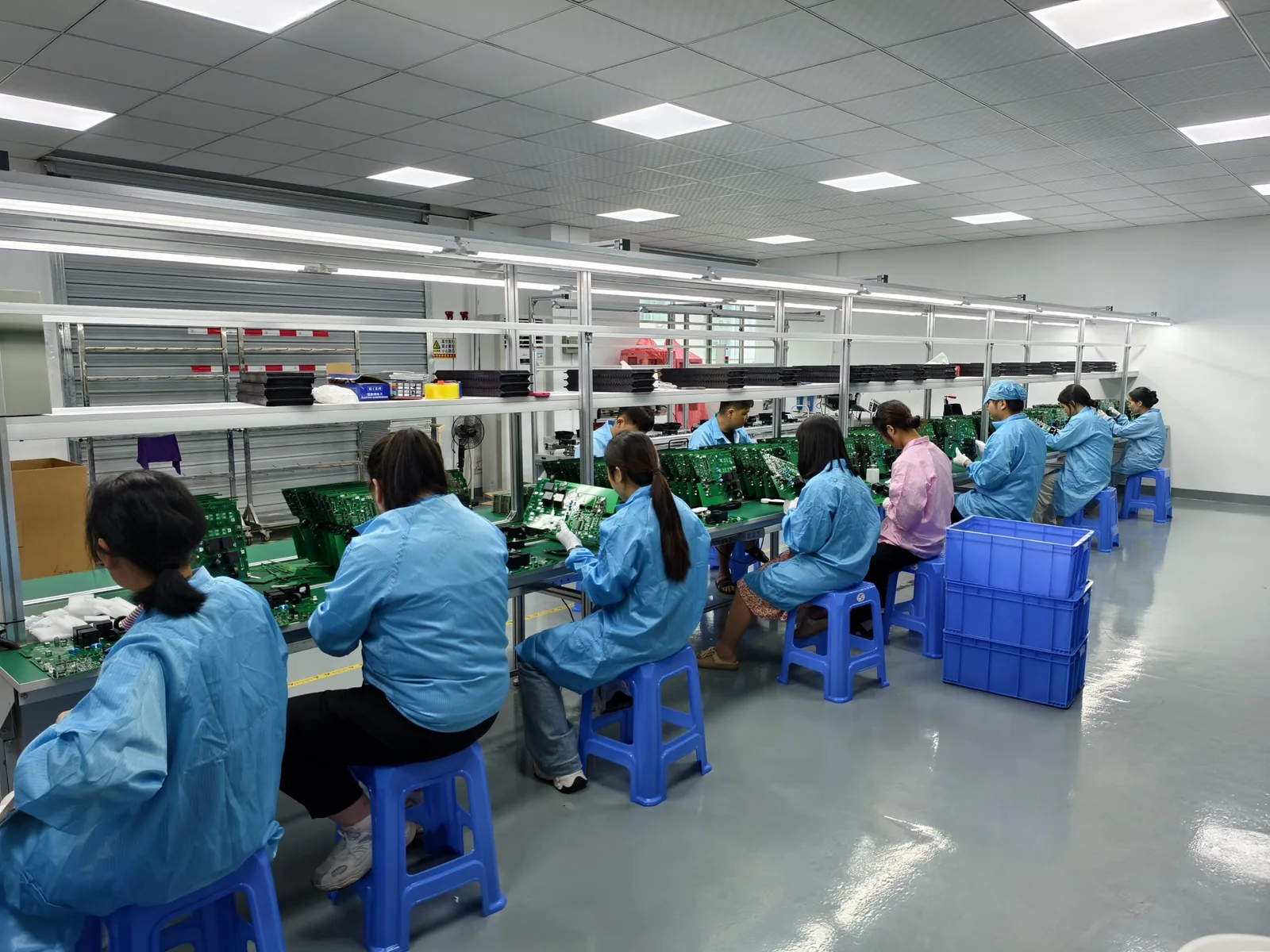
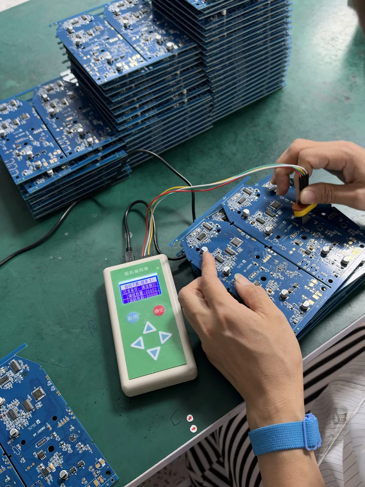

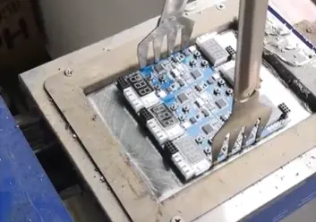
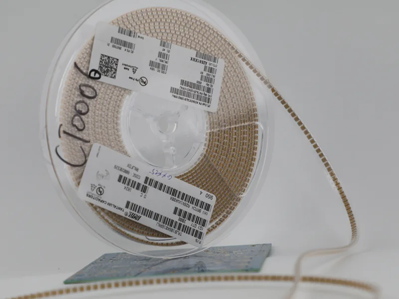

Follow the assembly line.
Each stage addresses a different production task. The route is prepared around the board construction, package mix, soldering requirements and agreed inspection plan.

Automatic paste printing
The stencil and printing process establish the paste deposits before placement. Alignment and process settings are reviewed for the pad geometry and component mix.

3D solder paste inspection
SPI checks paste deposits before the next assembly stage. Inspection settings help identify printing issues early in the process.
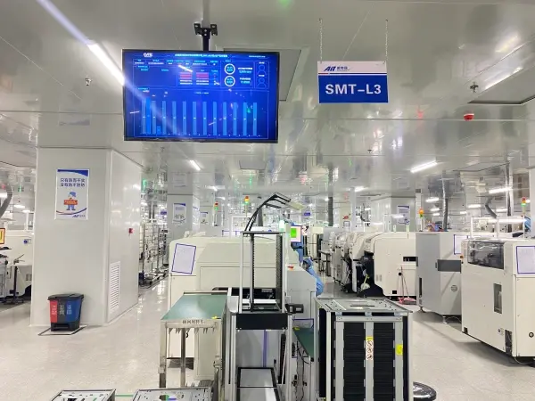
SMT placement
Seven SMT lines and Yamaha YRM20 placement resources support surface-mount builds. Placement preparation uses the approved BOM, component information and board data.
Reflow, DIP and manual soldering
Reflow temperature and conveyor settings are controlled for the assembly process. Through-hole work uses DIP and wave-soldering resources, with fixture preparation and manual soldering where the product needs it.
Two DIP lines and two manual soldering lines support this part of the build. Process engineers review the tooling and soldering route for mixed-technology assemblies.
Through-hole assembly →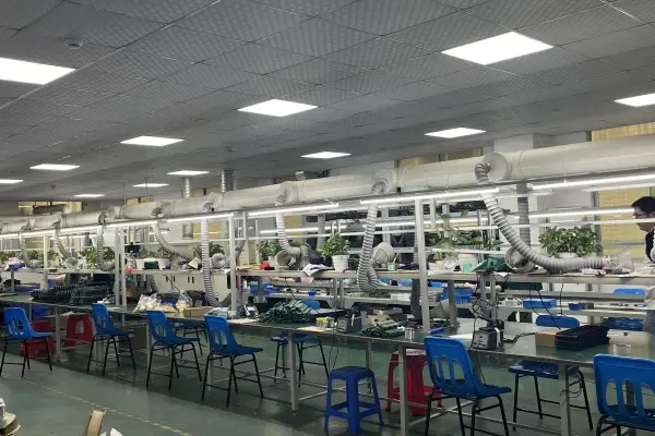
What the equipment supports.
A machine name is one part of the manufacturing decision. Confirm the construction, package requirements and acceptance plan for your actual design.
| Resource | Configuration / method | Role in your build |
|---|---|---|
| SMT 어셈블리 | 7 production lines; Yamaha YRM20 placement resources | Surface-mount placement from approved board and component data. |
| Paste printing & SPI | Automatic stencil printing; 3D solder paste inspection | Prepare and check the paste deposits before placement. |
| 리플로우 납땜 | Controlled temperature and conveyor settings | Form solder joints with a process matched to the assembly. |
| DIP / through-hole | 2 DIP lines; wave-soldering and insertion resources | Assemble connectors and other through-hole components. |
| Manual soldering | 2 manual soldering lines | Support assemblies and process steps requiring manual work. |
| Optical & hidden-joint inspection | AOI and X-ray | Check visible assembly features and selected hidden solder joints. |
| IC 프로그래밍 | Offline and in-circuit programming | Load the approved firmware using the project programming method. |
| Electrical & functional testing | ICT and FCT to customer requirements | Verify the agreed electrical checks and operating functions. |
| Additional reliability tests | Aging, temperature, humidity and drop testing by arrangement | Evaluate the conditions defined in the customer’s test specification. |
Coverage, fixtures, sampling and report requirements are confirmed for the order. Not every method is needed on every board.
Inspect the assembly.
Verify the agreed function.
Visual inspection, hidden-joint imaging and electrical testing answer different questions. We combine the methods relevant to your product and define the records needed for acceptance.
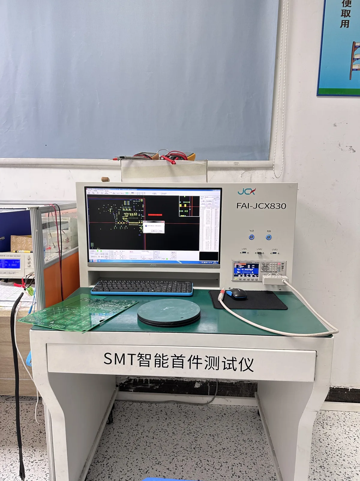 Build preparation
First-article review
Review component identity, placement and orientation at the start of a build. Agree any approval or hold point before the remaining batch.
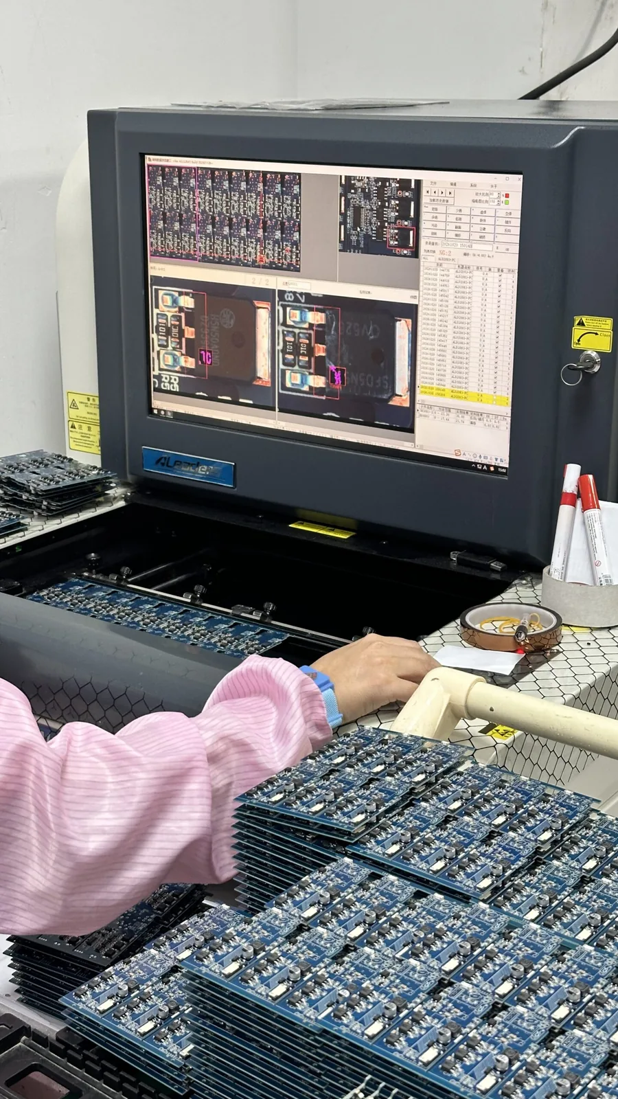 Assembly inspection
AOI & X-ray
AOI checks visible features. X-ray supports review of hidden joints beneath packages such as BGAs. Inspection criteria belong to the project plan.
 Product verification
ICT & functional test
Define the test access, fixture, firmware, operating conditions and pass/fail limits. Customer-requested environmental tests can extend the scope.
Plan the records with the build.
Discuss the documentation your receiving, engineering or quality team needs before production begins.
- PCB and BOM revision identification
- First-article and inspection requirements
- Firmware and test-program revisions
- Pass/fail results and outgoing report scope
Control the inputs.
Prepare for a repeatable build.
The manufacturing file, component choice and programming instruction are as important as the equipment on the floor.

File & manufacturing review
Review Gerber data, hole spacing, board construction, assembly information and electrical requirements. Resolve open DFM questions before releasing files.
Component sourcing & incoming inspection
Procure to the agreed BOM and sourcing requirements. Inspect incoming components and obtain customer approval before using proposed alternatives.
Process preparation
Prepare the printing, placement, reflow and through-hole route. Coordinate assembly tooling, programming and the inspection plan.
Configuration & release
Use the approved firmware and test procedure. Review specified test results, packaging and outgoing documentation before shipment.
Manufacturing backed by
defined quality requirements.
Our quality and management credentials support supplier qualification. Match the certificate scope, manufacturing location and board requirements to the work you are buying.
Quality management
Management of the processes that support consistent manufacturing and customer requirements.
Medical-device quality management
Quality-system requirements relevant to medical-device manufacturing within the certified scope.
Automotive quality management
Automotive-sector quality management within the applicable certification and site scope.
Environmental management
A management framework for environmental aspects of the operation.
Occupational health & safety
Management of occupational health and safety within the applicable scope.
Applicable PCB recognition
Review the relevant UL file and recognized board construction for the specified product.
IPC acceptance
Agree the document, revision and class for bare-board or assembled-board acceptance. IPC criteria are distinct from management-system certification.
RoHS & REACH documentation
Specify the material compliance documents required for your project. Finished-product approvals are addressed separately.
Find the area relevant
to your supplier review.
Use the equipment categories to prepare a more focused conversation about board construction, assembly and testing.
PCB fabrication equipment
Discuss the process route for materials, drilling, lamination, plating, finishing and board verification.
Explore fabrication resources →02 / PCBASMT & assembly equipment
Review paste printing, placement, soldering and inspection resources for the assembly requirements.
Explore assembly resources →03 / VERIFICATIONTesting laboratory
Discuss fixtures, test methods, pass/fail limits and the records your product needs.
Explore testing resources →
Plan a factory visit
or supplier review.
A useful factory discussion starts with your product and the questions your team needs answered. Share the manufacturing scope, the areas you want to review and your preferred dates so our team can coordinate the next step.
Production review
Board construction, assembly route, package mix, production stage and target quantities.
Quality & documents
Current certificates, acceptance requirements, inspection coverage and required records.
Project preparation
File readiness, BOM availability, firmware, fixtures, test requirements and delivery expectations.
Before your
manufacturing review.
Where is FLJ PCB based?
FLJ PCB / Philifast is based in Shenzhen, Guangdong, China. The company is Shenzhen Philifast Electron Co., Ltd., established in 2005. Contact the team to confirm the meeting location and visit arrangements.
What assembly resources does Philifast operate?
Our assembly resources include seven SMT production lines, two DIP / through-hole lines and two manual soldering lines, with Yamaha YRM20 placement equipment and supporting soldering, inspection and testing resources.
Do all boards go through every test listed here?
No. The inspection and test plan is selected for the design and customer requirements. Confirm coverage, sampling, test access, fixtures, firmware and report requirements before manufacturing.
Can we review quality certificates and production records?
Discuss current certificates and their applicable entity, site and scope with our team. Include the inspection and production records your supplier-qualification or receiving process requires in the project review.
What information helps you review our project?
Send the fabrication data, PCB specifications, BOM and assembly files where applicable, quantities and desired delivery. Add firmware, test requirements, product drawings and the questions you want the factory team to address.
Let’s review your next build.
Share the files, specifications and manufacturing questions. We will help define the production and test scope.