


With the birth and development of FPC and PCB, a new product called rigid-flex board has emerged.
What is Rigid-Flex PCB?
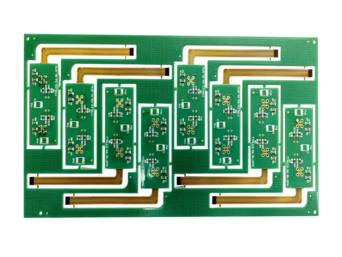
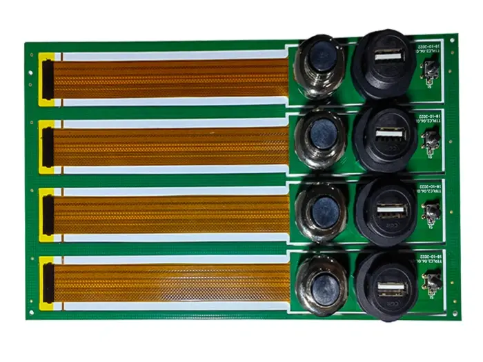
Rigid-flex boards combine flexible circuit substrates and rigid circuit substrates in one laminated structure. Rigid-flex PCBs cross the boundaries of traditional rigid PCBs. They also use flexible circuits that are made by patterning highly ductile, electrodeposited or rolled-annealed copper on flexible insulating films. Rigid-flex designs show some clear traits: high density, fine traces, small vias, small size, light weight, and high reliability. Their performance stays stable under vibration, shock, and humid conditions. They can bend, and they allow three-dimensional mounting. They use space inside an assembly more effectively. For these reasons, they are widely used in portable digital products such as mobile phones, digital cameras, and camcorders. Rigid-flex boards will be used more where package size must be reduced, especially in consumer electronics.
At first, the basic design ideas and manufacturing processes for multilayer rigid-flex boards came from aerospace equipment. Aerospace systems need reliable wiring inside very limited space. In some complex products, rigid-flex boards have even used more than 30 conductor layers. On the other hand, consumer electronics like phones and digital cameras always needed high density and low cost wiring. That need pushed new design ideas and manufacturing methods to appear.
A multilayer rigid-flex board is basically a mix of rigid boards and flex boards. But for board makers to join them well, they need good skills in both rigid PCB and flexible PCB processes. So, before designing this type of PCB, you must clearly know the manufacturer’s capabilities and limits.
Drawbacks of rigid-flex boards
If you only compare “flex board + rigid board + connector” with a single rigid-flex board, the main drawback of rigid-flex boards is cost. Rigid-flex boards often cost more. In some cases, the rigid-flex option may be almost twice the price of separate flex and rigid boards. However, if you remove the connector cost or the HotBar soldering cost from the comparison, the price can become close. To see the real cost picture, you must do a full cost analysis that counts parts, assembly steps, and special processes.
Another downside is assembly. SMT mounting and reflow of components on rigid-flex boards may require carriers or fixtures to support the flexible areas. Using carriers adds to SMT assembly cost. Carriers help keep the flex portions flat and supported during pick-and-place and reflow.
Advantages of rigid-flex boards
Beyond cost, rigid-flex boards have many advantages. Here are some of the main benefits:
-
Save board space and remove the need for connectors or HotBar processes
Because the flex and rigid parts are one piece, you can remove a connector or a HotBar joint. For high density designs, losing the space of one connector is very valuable. Removing connectors also lowers parts cost and the cost of HotBar processing. Moreover, the gap between two boards can be much smaller when you do not need a connector. -
Shorter signal paths, higher speed, and improved reliability
With separate rigid boards joined by connectors, a signal path looks like: board → connector → flex → connector → board. With a rigid-flex board it becomes: board → flex → board. The path is shorter. Signals cross fewer different materials, so they lose less energy. On standard rigid boards, traces are copper. Connectors have gold plated contacts. Soldered pins are usually tin or tin alloy. Signal changes at each material interface cause some loss. If you use rigid-flex, you reduce the number of interfaces. That helps signal integrity. For products that need precise signals, rigid-flex boards improve reliability. -
Simplify product assembly and save assembly time
Using rigid-flex boards can reduce SMT and final assembly time. You place fewer connectors. You also remove the assembly step of inserting a flex into a connector or the HotBar soldering step. Fewer parts means a shorter BOM. That reduces inventory and parts management work.
How production and assembly differ for flex and rigid-flex boards
The main SMT process is similar for all board types. Flexible circuits, rigid-flex boards, and rigid boards all go through component placement and reflow soldering that uses solder paste. But flexible boards and rigid-flex boards have special needs. If these extra needs are not met carefully during production, you will get big problems.
1. Solder paste printing
Like rigid PCBs, you use a stencil and a solder paste printer to apply solder paste to flex and rigid-flex boards. Many SMT operators worry about size control and the fragility of flex boards. Unlike rigid boards, flex board surfaces are not flat. So you need fixtures and alignment holes to hold them in place. Also, flexible circuit materials change size with temperature and humidity. They can stretch or wrinkle by about 0.001 inch per inch under some conditions. These stretches and wrinkles cause shifts in the board position in X and Y. For this reason, flex placement often needs smaller carriers or special tooling than rigid board SMT.
2. SMT component placement
Today, components are getting smaller. Small parts can cause problems in reflow if the board surface is not flat. If a flex circuit is small, dimensional changes may be less of a problem, but you may still need smaller SMT carriers or extra fiducial marks. If a carrier is not flat, you will see placement shifts. A good SMT fixture helps keep the placement surface flat and steady.
3. Reflow soldering
Before reflow, flexible circuits must be dried. This is a key difference between flex and rigid board assembly. Flex materials absorb moisture like a sponge. They can gain up to about 3% of their weight from moisture. Once a flex board soaks up moisture, you cannot reflow it without drying first. Rigid boards also have this issue, but rigid boards tolerate some moisture better.
Flexible circuits require a pre-bake at roughly 225°F to 250°F (about 107°C to 121°C) for a short time, ideally finished within one hour. If you do not dry the flex in time, you must store the boards in a dry box or in nitrogen storage until they are baked. Proper drying prevents damage caused by steam formation during reflow, such as delamination or blisters.
Applications of rigid-flex boards
Rigid-flex PCBs combine the durability of rigid boards with the adaptability of flexible boards. Among all PCB types, rigid-flex is the most robust for harsh environments. Because of that strength, rigid-flex boards are popular in industrial control, medical devices, and military equipment. Mainland manufacturers are also increasing the share of rigid-flex boards in their total output.
Typical application areas include:
-
Industrial use — This includes industrial machines, military equipment, and medical devices. These parts need precision, safety, and durability. Rigid-flex boards for these fields must deliver high reliability, high precision, low impedance loss, complete signal quality, and long life. But the process is complex, output is low, and unit cost is high.
-
Mobile phones — In phones, rigid-flex boards appear in hinge areas of folding phones, camera modules, keypads, and RF modules. They handle repeated bending and tight assembly space.
-
Consumer electronics — Digital still cameras (DSC) and digital video (DV) products are typical consumer items that use rigid-flex. We can look at rigid-flex from two angles: performance and structure. From the performance side, rigid-flex can link different rigid boards and modules in three dimensions. So with the same line density you increase the usable circuit area. That raises the circuit carrying capacity and reduces signal path limits and assembly mistakes. From the structure side, rigid-flex boards are light and thin and allow flexible routing. They help shrink size and cut weight.
-
Automotive — In cars, rigid-flex boards are used for key switches on the steering wheel, connections between in-vehicle screens and control boards, door control keys, car audio controls, parking radar camera systems, many sensors (air quality, temperature and humidity, gas detection and control), vehicle communication systems, satellite navigation, connections for rear seat controllers, front end controller boards, and even external detection systems.
Materials for multilayer rigid-flex boards
Below is a simple table of common materials used to make multilayer rigid-flex boards. I list the needed material, the traditional choice, and higher performance choices.
| Needed material | Traditional material | High performance material |
|---|---|---|
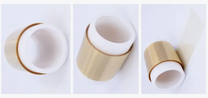
| Flexible substrate (FCCL) | Traditional polyimide film | New polyimide film |
| Double-sided copper laminate | Polyimide core with acrylic adhesive (or epoxy adhesive) | Glue-free polyimide laminate (cast type or laminated type) |
| Coverlay | Traditional polyimide coated with acrylic or epoxy adhesive | New polyimide coated with hot-melt polyimide adhesive |
| Adhesive film (bonding film) | Acrylic resin adhesive film, epoxy adhesive film, polyimide film coated both sides with acrylic adhesive | New polyimide film coated both sides with hot-melt polyimide resin |
| Rigid substrate (CCL) | Glass-epoxy (fr4) | Glass-BT resin board, glass-polyimide resin board |
The table above lists several materials that are necessary when making rigid-flex boards. It is important to note that with technology progress, the performance of these materials has improved significantly.
Materials must have high heat resistance and good dimensional stability during heating. For high-reliability fields like military and aerospace, we recommend using thicker polyimide film (greater than 50 μm). In these areas, the base material must have strong stability and durability during processing. In contrast, consumer electronics often follow a trend to be thinner and lighter. There, manufacturers usually use thinner dielectrics (less than 50 μm).
Among adhesive copper clad laminates, coverlays, and bonding films, acrylic adhesives have better bond strength but slightly lower heat resistance and higher shrinkage. Epoxy adhesives offer better heat resistance, but they take longer to cure and sometimes have slightly weaker bond strength.
Using cast or pressure-laminated glue-free copper clad laminate usually gives higher heat resistance and lower coefficient of thermal expansion (CTE). These materials also help reduce final board thickness and can significantly reduce drilling resin smear. However, the glue-free material requires processing above 300°C and needs special equipment and process control.
Notes and extra tips for designers and buyers
-
Talk to your board maker early. Tell them how many rigid and flex layers you plan, where the bend areas are, and how many flex cycles the board must survive. Also tell them target impedance and high speed needs. The manufacturer can then tell you if the design is doable and what limits exist.
-
Keep bend areas free of rigid parts and heavy components. Use clear bend lines and keep traces near the neutral axis when you can. Traces across bending areas should be wide enough and follow good flex rules. Avoid plated through holes in repeated bend areas unless you use special designs.
-
Design for assembly. If you expect SMT on the flex area, plan for carriers, fiducials, and bake steps. Mark areas that need stiffeners and where you will use adhesives to support components.
-
Choose materials by need. Use thicker polyimide and stronger base materials for military or medical. Use thin dielectrics for phones and light consumer goods if you need low weight and small size.
-
Cost tradeoffs. Rigid-flex can cut assembly parts and connectors, but the board itself can cost more. Do a whole system cost check. Often the total system cost falls when you remove connectors and the related assembly steps. Also consider repair and test costs.
-
Do stress tests. If your product will face vibration, shock, heat, or humidity, test the rigid-flex board early. Cycling tests, thermal shock, and humidity testing will find issues before mass production.
-
Plan for tooling. Work with the PCB maker to plan jigs, carriers, and bake schedules. Proper tooling reduces defects and placement errors.
-
Documentation. Provide clear mechanical drawings, stackup, bending rules, and layer maps. Show where stiffeners go and where flex tails exit the rigid area.