
Rigid-Flex PCB
Manufacturing
Rigid where components belong.
Flexible where the connection needs to go.
FLJ manufactures custom rigid-flex printed circuit boards for compact electronic assemblies. Rigid circuit regions and flexible interconnections form one integrated board, from prototypes to production.
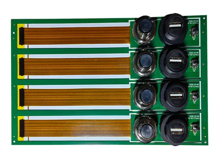
One Circuit Across Multiple Rigid Sections
The component layout can occupy more than one plane. Rigid-flex brings those planes together without making every connection a separate cable assembly.
A rigid region provides the mounting surface and routing layers for components, connectors and mounting features. The integrated flex section carries the circuit onward to another rigid region. Once fabricated and assembled, the board can take its installed shape around the mechanical layout.
More room for the product
Link a main board to an offset sensor, place controls against a front panel, or connect functional regions around an enclosure. The flexible connection lets each rigid area sit where its function belongs.
Fewer separate interconnect parts
Instead of terminating a cable at each board, the integrated flex circuitry carries the connection between rigid regions. Where it replaces a separate interconnect, that removes its mating interfaces and the associated termination and installation work.
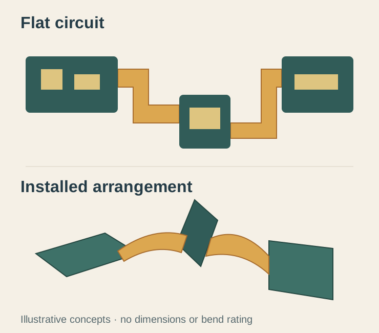
Rigid-Flex Constructions for Your Assembly
A six-layer rigid region can contain a two-layer flexible core that continues into the exposed interconnect. The other copper and dielectric layers remain within the rigid areas. The example below illustrates that regional distinction; the layer counts and arrangement are selected for the actual board.

Rigid-region routing
Additional copper and dielectric layers provide routing and component mounting within the rigid sections. Plated connections join the required layers and the flexible circuitry.
The flexible connection
The selected flex layers continue between regions. Its thickness, copper arrangement, protection and path work together to suit the installed geometry and any movement in service.
The whole configuration
Choose the number and shape of rigid regions, their local thicknesses and the flexible interconnection. Where dense devices need selective layer connections, HDI fabrication can form part of the rigid-region design.
Rigid-flex, reinforced flex or semi-flex?
| Construction | What creates the supported area | What it means for the product |
|---|---|---|
| Rigid-flex PCB | Routed rigid circuit layers integrated with the flexible circuit. | Rigid component regions and flexible interconnects belong to one circuit-board construction. |
| Flex with a stiffener | A local reinforcing material bonded to a flexible circuit. | Support for a connector, mounting or assembly area. The stiffener itself does not add routed circuit layers. See Flexible PCB Manufacturing. |
| Semi-flex PCB | A locally thinned region in a rigid-board material system. | A different construction for suitable installation bends; it is not a polyimide rigid-flex stack or a substitute for repeated-flex qualification. |
Materials and the Rigid-to-Flex Transition
The boundary between a rigid region and a flexible span is a small area with an important job: the circuit must leave a supported stack and enter a section that can bend.
- Rigid laminate
- The structural and electrical base for the rigid circuitry, selected for the thermal and electrical duty.
- Flexible laminate
- Polyimide and copper form the continuing interconnect. Base-laminate construction and copper properties influence the flex section.
- Coverlay
- Protects the flexible conductors, with openings and terminations matched to the local construction.
- Bonding material
- Joins the regional layers while its thickness, cured properties and resin flow contribute to the finished structure.
Manage the edge, the bond and the bend together.
Controlled-flow or no-flow prepreg bonds the rigid-region layers while limiting the resin that can enter the flexible window. Flow remains a material and process property: enough bonding material must remain at the interface without creating an unwanted hard edge across the flex. Coverlay termination and the local bonding arrangement complete that boundary.
In the rigid region, the adhesive content and material arrangement affect expansion through the thickness during heating. Plated holes cross that structure, so the thermal behavior of the stack influences the strain imposed on the hole-wall copper. Adhesiveless flex laminate and an appropriate selective-coverlay construction can reduce unnecessary adhesive within the rigid region, while preserving the bonding and protection the product needs.
The bend path belongs beyond the supported edge, with geometry that avoids a sharp crease against the rigid boundary. Conductor routing, local layer thickness and the placement of holes and components all affect how strain reaches the copper and solder joints. A circuit formed once during installation has a different mechanical duty from an interconnect moving throughout its operating life.
Manufacturing and Verifying the Integrated Board
Rigid-flex fabrication brings thin flexible circuitry, locally rigid layers and regional openings into the same finished article. Registration and protection follow the construction through each operation.
Form the flexible circuitry
The selected flexible laminate is imaged and etched to create its conductor patterns. Thin-material handling and registration keep the circuit positioned for subsequent coverlay and regional assembly.
Build the rigid regions
Prepared rigid layers, flexible circuitry and bonding materials are aligned and laminated. Regional tooling and support hold the stack while the bond is formed. The construction determines the window preparation and final opening sequence, leaving the intended flexible span clear of the rigid build.
Complete the connections
Drilling, hole preparation and plating form the specified interlayer connections. Outer circuitry, surface finishing and profiling complete the board, with protection for flexible regions through the relevant operations.
Verify the finished board
Checks address regional registration, the finished outline and thicknesses, coverlay and transition features. Electrical testing verifies the required connectivity and isolation.
Look at the connection inside the structure
Cross-sectional examination evaluates the interfaces that are hidden in the finished board: laminate bonds, regional registration and plated connections. For controlled-impedance circuits, the conductor geometry and reference arrangement carry through into the verification scope.
Thermal and mechanical qualification address the intended materials, construction and operating conditions. For a moving interconnect, the bend geometry, travel and repeated use form part of that evaluation; a continuity check answers a different question.
For design details before release, DFM / DFA Review connects the regional fabrication plan with the component and assembly layout. PCB Testing covers the wider inspection and test offering.
From Prototype Fit to Production Assembly
FLJ supplies rigid-flex bare boards and can continue into component sourcing, assembly and testing. This brings the circuit construction and the populated product through a connected manufacturing route.
Prove the physical arrangement
Prototype boards let the product team check the rigid-region positions, flexible path, mounting and mating features in the enclosure. A useful trial considers both the flat board used for processing and the formed arrangement used in the product.
Assembly support and carriers hold the board appropriately through component placement and soldering. Production carries forward the selected construction and assembly definition, with handling and packaging suited to the connected regions and exposed flex.
Explore PCB assembly services →Bring the regions together.
Share your circuit files, outline and quantity, together with the intended installed shape and any movement in service. FLJ can quote the bare board or include sourcing, assembly and testing for the finished product.
Related rigid-flex PCB designs
Explore the board images, product information and design details for related projects.


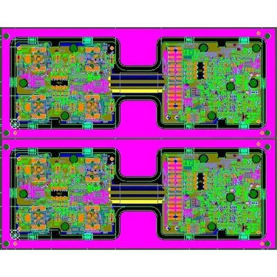
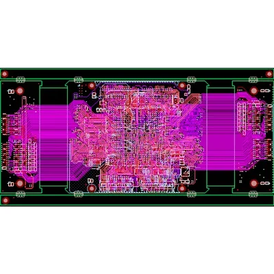
Medical Equipment Rigid-Flex PCB Design
A rigid-flex PCB design profile for medical equipment.