
















ICT vs Flying Probe vs Functional Testing: How to Specify a PCBA Test Plan
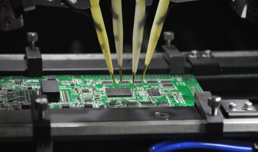
PCB assembly testing methods answer different fault questions: ICT and flying probe test selected electrical nodes and components on an assembled board; functional testing checks whether the powered assembly performs a defined job. ICT uses a dedicated fixture with many contacts, while flying probe moves contacts between accessible points. Functional test uses a product-specific stimulus and expected response. The three methods can complement one another because they do not reveal the same faults or give the same diagnostic detail.
Choose the plan from the failures you must catch, the test points the design exposes and the expected build volume. Philifast’s PCBA testing guide introduces the methods. This article helps turn that list into a test specification for an actual assembly.
Start with the fault, not the machine name
| Need | Likely method | Important limit |
|---|---|---|
| Find a short, open or wrong passive value at reachable nodes | ICT or flying probe, depending on access and program/fixture economics | Neither tests every inaccessible net or every end-use behavior. |
| Repeat structural tests across a stable production run | ICT may justify a dedicated fixture | Fixture design and maintenance take time and cost; coverage still depends on design access. |
| Test prototypes or frequent revisions without a dedicated bed-of-nails fixture | Flying probe may be attractive | Moving probes can take longer per board and need reachable test locations. |
| Verify boot, communications, outputs, calibration or a system sequence | 機能テスト | A pass may not identify the precise bad component; the test only covers programmed cases. |
Sierra’s flying-probe guide explains the moving-probe approach; Matric’s ICT/flying comparison describes the fixture trade-off. Actual cycle time and coverage depend on the board, access and test program, so vendor price-per-board examples should not be copied into an RFQ.
“Coverage” also needs a denominator. A report may count contacted nets, testable components, specified faults or product functions; those figures cannot be compared as if they were the same percentage. Ask the test engineer to list the specific fault classes and nodes or functions tested, then record the exceptions. A probe can touch a net yet still be unable to isolate every component connected to it. Conversely, a passing functional sequence may exercise a circuit without revealing which component would fail under a different operating condition.
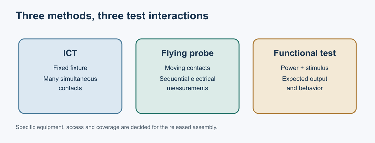
Illustration: Conceptual contact and stimulus methods, not Philifast equipment.
Why the methods often belong together
An electrical structural test can locate a wrong resistor or shorted net before power is applied. A functional test can then check whether the programmed controller, interface and outputs behave as expected. If functional test alone fails, diagnosis may take longer because many component-level faults can produce the same bad output. Conversely, a board that passes ICT may still have a firmware, calibration or system-behavior issue that ICT was never designed to detect. PCBElec’s ICT/FCT comparison makes this distinction.
A useful sequence is often inspection, a controlled unpowered or low-risk structural check, programming where required, then powered functional verification. The exact order depends on product design. An obvious short should normally be investigated before applying full power; a programmed microcontroller may need its image loaded before the intended functional test can run. Define how failed boards are isolated, diagnosed, repaired and retested, including whether the complete sequence or only affected steps must repeat. Otherwise a “100% tested” statement says little about the delivered units.
Optical and X-ray inspection add evidence about visible and hidden assembly features. They are not substitutes for powered behavior. Bare-board electrical testing is a separate stage before components are fitted; Philifast’s PCB testing-items article covers that fabrication context.
Consider a hidden BGA solder joint with intermittent contact. Optical inspection cannot see it. A structural electrical test may detect an open if the affected net and test condition expose it, and a functional test may fail if that connection is exercised. Neither result alone describes the joint’s physical condition. Inspection and electrical evidence answer different questions, which is why coverage should be built from a fault list rather than a single machine label.
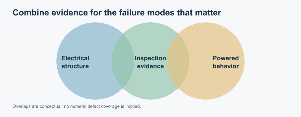
Illustration: Coverage is product-specific. The circles indicate complementary questions, not a percentage of defects detected.
A simple volume decision
For an early prototype or changing design, programming flying probe and a focused functional check may be easier to change than building an ICT fixture. For a stable, repeated production run, an ICT fixture may spread its design cost over more boards and shorten repetitive structural checks. This is an economic starting point, not a universal quantity threshold. A dense board with poor access may limit both structural methods even at high volume; adding test points in the next revision can be more effective than trying to solve access solely in software.
The economic comparison should include fixture design and maintenance, test-program creation, debugging, per-board cycle time, operator handling, expected revisions and failure-diagnosis time. Keysight’s ICT/flying-probe discussion explains why fixed contacts often favor repeated high-volume checks and moving probes favor changeability. A new board revision can require an ICT fixture change; a flying-probe program is usually easier to update, but still needs validation against new CAD data and a known-good board.
A board with limited access
Suppose a compact PCBA has few exposed pads, a BGA, connectors on both sides and a shield added late in design. A test engineer cannot promise high ICT coverage simply by building a fixture; the fixture still needs safe, repeatable access. Flying probe may reach some component pads but can be blocked by height or shielding. Functional test can check a subset of behavior through connectors, yet may give weaker fault isolation. The next design revision may need additional test points, a temporary assembly stage before shielding, or a revised test strategy. Ask for an access review during design, before committing to the method and budget.
Map each feared fault to evidence and a blind spot
Start by naming plausible faults for this design: open or shorted connections, wrong or missing parts, reversed polarity, an incorrect value, a firmware mismatch, a power-up failure or a product function that is outside its allowed response. For each one, ask what observation would detect it, at which production stage, and what happens if the observation is inconclusive. This turns “test the board” into a test objective that can be reviewed by design, manufacturing and quality.
ICT can check selected component and connection behavior when suitable electrical access exists and the circuit can be measured under the chosen test conditions. Its fixture does not make inaccessible nodes observable by itself. Flying probe can reduce dedicated fixture hardware and reach selected points, but access, test-program effort and cycle time depend on the actual board and test requirements. Functional test can exercise defined powered behaviors through interfaces, but a passing response may not isolate every internal defect. Each method therefore needs a stated coverage boundary.
Combine methods when the risk calls for evidence at different stages. A wrong paste deposit is observed before reflow by SPI; a BGA joint’s geometry may require X-ray; selected electrical faults may be covered by ICT or flying probe; product-level behavior may need a functional test. These results answer different questions and should not be added into one unexplained “coverage percentage.” The SPI guide そして BGA X-ray guide explain the boundaries of those inspections.
Avoid confusing an unpopulated-board electrical test with a populated assembly test. IPC-9252 addresses electrical testing of unpopulated printed boards, not the full ICT or functional test of an assembled PCBA, and IPC lists it as no longer maintained. Check the IPC revision table before invoking any standard and name the correct test object in the RFQ.
The point in the manufacturing route matters too. Bare-board electrical test checks the fabricated interconnect before components are mounted. ICT and flying probe on an assembly evaluate selected electrical behavior after placement and soldering. Functional test usually needs a defined powered state and may require firmware, fixtures, loads or interfaces. A final product test can cover behavior that is invisible to an unpowered continuity check, but it may be too late to isolate which manufacturing step created a fault. Choose the sequence so each test catches the defect at a useful point for containment and diagnosis.
Document any intentional test exclusions. A high-impedance node may not tolerate a conventional measurement, an in-circuit reading can be affected by parallel paths, and an inaccessible connection may remain untested without a design change. Record the reason and the compensating evidence, if any, so a later reviewer can distinguish an approved limitation from a test-program omission. Never infer comprehensive fault coverage from the presence of a test station or a passing label.
Set the retest rule before failures arrive. Decide whether a failed board is held for debug, repaired and retested, or scrapped; identify who may approve a deviation and whether the original result remains attached to the serial number. Repeated retests can create a misleading impression if only the final pass is retained. If a repair changes the circuit or firmware, define whether the complete test sequence must run again or whether a focused retest is acceptable under the quality plan.
Keep the test record attached to the product configuration
A useful result identifies the serial number or controlled panel position, PCB and BOM revisions, firmware/build, test-program and fixture revisions, date, measured values where relevant, and pass/fail for each defined step. If a board is debugged and retested, preserve both runs and the failure disposition. Replacing a failed result with a later pass hides whether a process correction or a test-program change produced the outcome.
Define how limits are selected and maintained. Functional limits should come from the design authority’s approved requirements, not from an operator’s memory of a known-good board. Electrical limits should account for the measurement method and applicable circuit conditions. If a test program changes, record what changed, who approved it and whether previously built units need to be re-evaluated. A report that contains only “PASS” cannot show which version of the procedure produced that status.
Design test access before the layout is frozen
An access review is most useful while test points and mechanical constraints can still change. Identify required nets, safe probe locations, no-probe regions, connector access, board support, shield or enclosure effects, power sequencing and any sensitive devices. Consider whether test happens while the boards remain panelized or after depaneling; that decision changes fixture support and unit identification. A late shield, component height or stiffener can block points that looked accessible in the layout.
Ask the test engineer to return a coverage statement that lists covered faults or nets, untested areas, assumptions, development effort, expected record and failure-disposition path. Have the design authority approve residual risk explicitly. That record is more useful than choosing ICT, flying probe or functional test by machine name alone.
Data a test engineer needs from the design team
Send the released schematic, BOM, placement data, PCB design or netlist, test-point map, connector pinout, power sequence, firmware/build version and expected functional behavior. Mark no-probe areas and sensitive nodes. Define which rails can be powered during test and which components must not be stressed. Provide known-good limits and pass/fail criteria for each functional step, rather than “test that it works.”
For functional test, write observable steps: input stimulus, load or fixture, allowable response, time window, environmental condition if relevant, and required record. “Communications work” is ambiguous; “the programmed board responds to command X at interface Y within the approved limit” is testable once the limit and protocol version are specified. Include calibration and serial-number handling when they affect acceptance. For structural tests, identify nets excluded because of inaccessible nodes, components that cannot be measured in circuit, and any special handling for batteries or sensitive inputs.
Ask the manufacturer for a coverage statement listing tested and untested nets or functions, fixture/program nonrecurring effort, cycle time estimate, test records and failure-disposition process. An inaccessible node should be documented, not counted as covered by the mere presence of ICT or flying probe on the production floor.
Request a sample output record before production: board identifier and revision, test program/fixture revision, pass/fail by step, measured values where needed, timestamps and retest history. This makes the plan reviewable and prevents a silent change in test limits from masquerading as improved yield. If the product’s design changes, recheck both electrical access and functional limits before reusing the old coverage claim.
The best test plan is a set of explicit fault questions and evidence requirements. Request Philifast’s project-specific test proposal and confirm the available methods and coverage for the released assembly; public descriptions do not establish a universal equipment or coverage claim.