


1. Định nghĩa và phân loại điện tử ô tô
Bo mạch in (PCB) ô tô là các bo mạch in được thiết kế để sử dụng trong hệ thống điện tử của xe hơi. Hệ thống điện tử ô tô được chia thành hai nhóm chính. Một nhóm là hệ thống điều khiển điện tử thân xe. Nhóm còn lại là hệ thống điều khiển điện tử trong xe. Hệ thống điều khiển thân xe có thể được chia nhỏ thành các phần nhỏ hơn. Chúng bao gồm hệ thống điều khiển động cơ, hệ thống điều khiển thân xe cho cửa và đèn, và hệ thống điều khiển khung gầm. Hệ thống điều khiển thân xe kết nối các bộ phận cơ khí của xe với các bộ phận điện tử. Chúng cho phép các bộ phận điện tử làm cho các bộ phận cơ khí hoạt động tốt hơn. Chúng giúp xe vận hành mượt mà và an toàn hơn.

Hệ thống điện tử trong xe bao gồm hệ thống đa phương tiện, hệ thống định vị, camera hành trình, radar đỗ xe lùi và các hệ thống khác. Những hệ thống này giúp việc sử dụng xe trở nên thuận tiện hơn và bổ sung các tính năng giải trí. Chúng thay đổi cách thức lái xe và hành khách sử dụng phương tiện. Chúng cải thiện trải nghiệm người dùng tổng thể.
2. Nhu cầu ngày càng tăng do sự phát triển của trí tuệ nhân tạo trong ngành ô tô.
Khi xe hơi trở nên thông minh hơn, việc sử dụng bảng mạch in (PCB) trong ô tô cũng tăng lên. Các tín hiệu truyền tải nhanh hơn và ở tần số cao hơn. Do đó, PCB phải vừa hiệu quả vừa rất đáng tin cậy.
3. Ưu điểm cốt lõi của bo mạch in ô tô
PCB được sử dụng ngày càng phổ biến vì chúng mang lại nhiều lợi ích vượt trội. Chúng cho phép mật độ linh kiện cao. Do đó, chúng phát triển cùng với sự tích hợp cao hơn của mạch tích hợp và công nghệ lắp ráp tiên tiến. Chúng cũng rất đáng tin cậy. Nhiều quy trình kiểm tra, thử nghiệm và thử nghiệm lão hóa giúp chúng hoạt động ổn định trong thời gian dài mà không gặp sự cố. Điểm quan trọng nhất là PCB có thể được lắp ráp. PCB giúp việc lắp ráp các linh kiện tiêu chuẩn trở nên dễ dàng. Chúng phù hợp với sản xuất tự động và sản xuất hàng loạt. Bạn có thể lắp ráp PCB với các linh kiện khác để tạo ra các mô-đun lớn hơn, hệ thống và cả máy móc hoàn chỉnh.
4. Nhu cầu về PCB tăng cao trong các phương tiện năng lượng mới
So với xe ô tô truyền thống, xe ô tô năng lượng mới sử dụng nhiều bảng điều khiển điện tử hơn. Một mặt, hệ thống điện tử trong xe năng lượng mới đòi hỏi mức độ kiểm soát điện tử cao hơn so với hệ thống truyền động động cơ đốt trong truyền thống. Mặt khác, lõi của xe năng lượng mới là pin, động cơ và hệ thống kiểm soát điện tử. Các bộ phận này làm tăng hàm lượng điện tử lên mức cao hơn nhiều so với xe truyền thống. Hai yếu tố này làm tăng số lượng bảng mạch in (PCB) mà một chiếc xe cần. Chúng cũng đẩy các loại PCB từ bảng mạch giá rẻ sang bảng mạch có giá trị cao hơn. Giá trị của PCB ô tô trên mỗi xe tiếp tục tăng.

Yêu cầu quy trình cho bảng mạch in (PCB) trong ngành ô tô
1. Lựa chọn vật liệu
Đối với bất kỳ bảng mạch in (PCB) nào, chất lượng vật liệu có ảnh hưởng lớn đến chất lượng tổng thể của sản phẩm. Khi sản xuất PCB cho ô tô, bạn cần xem xét tác động của môi trường ô tô đối với vật liệu. Do đó, hãy lựa chọn vật liệu chất lượng cao cho PCB ô tô. Chọn những vật liệu có khả năng chịu được nhiệt độ cao và thấp, áp suất cao, cũng như các điều kiện khắc nghiệt khác.
Vật liệu nền có nhiệt độ chuyển pha cao (High-Tg): Sử dụng nhựa epoxy có nhiệt độ chuyển pha (Tg) ≥ 170°C. (Nhựa FR-4 thông thường có Tg khoảng 130°C.) Ở nhiệt độ 150°C, độ bền uốn giảm xuống chỉ còn khoảng một phần sáu so với vật liệu nền thông thường.
Polyimide (PI): Sử dụng vật liệu nền PI có nhiệt độ chuyển pha (Tg) lên đến 260°C gần bộ tăng áp. PI có thể chịu được môi trường cực đoan trong thời gian ngắn lên đến 200°C.
Chọn vật liệu có độ bền cao và ổn định lâu dài. Chọn vật liệu chịu được nhiệt độ cao, độ ẩm và tác động hóa học. Những lựa chọn này giúp mạch in (PCB) duy trì các tính chất điện và cơ học ổn định trong xe ô tô.
2. Quy tắc thiết kế
Sản xuất mạch in (PCB) cho ô tô là một quy trình phức tạp. Để sản xuất một PCB ô tô đúng tiêu chuẩn, cần tuân thủ nhiều quy tắc thiết kế và tiêu chuẩn sản xuất. Các nhà thiết kế PCB phải nắm vững các quy tắc này. Các nhà thiết kế phải tuân thủ chặt chẽ các tiêu chuẩn.
Bảng tổng hợp các thách thức, giải pháp và kết quả của các quy trình thông dụng:
| Những thách thức phổ biến | Giải pháp | Kết quả |
|---|---|---|
| Hỏng hóc do rung động | Lỗ xuyên qua có thành dày (lớp đồng ≥ 25 μm) và góc tròn. | Không có hiện tượng bong tróc sau một triệu chu kỳ rung động (gấp mười lần mức tiêu chuẩn cho người tiêu dùng). |
| Nút thắt cổ chai nhiệt | Các khối đồng nhúng và mảng lỗ vi mô (đường kính lỗ ≤ 0,2 mm). | Điện trở nhiệt cục bộ giảm 35%. Nhiệt độ tiếp điểm IGBT < 125°C. |
| Rủi ro hàn | Sử dụng hàn không chì SAC305 (điểm nóng chảy 217°C) và các pad mạ vàng. | Độ bền của mối hàn duy trì trên 95% ở 150°C. |
Công việc thiết kế cũng cần bao gồm bố cục, khoảng cách, kích thước pad, lỗ vias và giải pháp tản nhiệt. Sử dụng góc bo tròn cho đường dẫn và đặt lỗ vias đúng cách. Chú ý đến các lỗ gắn cơ khí và cạnh bo mạch. Thêm gia cố ở những vị trí bo mạch gắn vào khung xe. Đảm bảo bo mạch đáp ứng các yêu cầu về rung động và va đập của xe.
3. Quy trình làm việc
Trong quá trình sản xuất PCB ô tô, tuân thủ một bộ quy trình tiêu chuẩn. Điều này đảm bảo chu trình sản xuất diễn ra suôn sẻ. Theo dõi chi tiết tại từng bước. Thêm các điểm kiểm tra chất lượng tại các bước quan trọng để đảm bảo sản phẩm cuối cùng đáp ứng yêu cầu. Thực hiện kiểm tra trực quan, kiểm tra kích thước, kiểm tra điện và kiểm tra môi trường tại các điểm đã định. Sử dụng kiểm tra quang học tự động (AOI), tia X và kiểm tra bằng đầu dò bay để phát hiện lỗi sớm.
4. Hướng phát triển kỹ thuật
Ngoài các yêu cầu về quy trình nêu trên, hãy theo dõi các xu hướng công nghệ PCB mới nổi. Xe điện, hệ thống hỗ trợ lái xe tiên tiến và xe tự lái đang thúc đẩy sự phát triển của công nghệ PCB. Các hướng phát triển chính trong tương lai bao gồm:
Thiết kế bảng mạch đa lớp: Khi yêu cầu về chất lượng tín hiệu ngày càng cao, thiết kế bảng mạch đa lớp trở nên phổ biến hơn. Số lượng lớp tăng giúp cải thiện việc định tuyến tín hiệu và tiếp đất, đồng thời giúp kiểm soát trở kháng.
Truyền tín hiệu tốc độ cao: Xe hơi cần trao đổi thông tin nhanh hơn. Thiết kế tín hiệu tốc độ cao là công nghệ cốt lõi. Điều chỉnh trở kháng, sử dụng vật liệu điện môi được kiểm soát và đặt các lớp đất đúng cách.
Tối ưu hóa kích thước và thiết kế nhẹ: Các nhà sản xuất ô tô đang hướng tới việc sử dụng các bộ phận nhỏ gọn và nhẹ hơn. Bo mạch in (PCB) phải đáp ứng các yêu cầu mới về chi phí và độ ổn định. Bo mạch mỏng hơn và thiết kế gọn nhẹ giúp tiết kiệm không gian và trọng lượng.
Tổng thể, mạch in (PCB) trong ngành ô tô đòi hỏi các tiêu chuẩn kỹ thuật và quy trình sản xuất cao. Bạn cần xem xét nhiều yếu tố để đáp ứng những yêu cầu này. Chỉ khi đó, bạn mới có thể đảm bảo hiệu suất và chất lượng của PCB. Khi công nghệ ngày càng phát triển, ngành ô tô sẽ tiếp tục trở nên thông minh hơn. Ngành PCB cũng sẽ tiếp tục đổi mới và cải tiến.
Định tuyến nguồn và đất cho bảng mạch in điện tử ô tô
Trong các hệ thống âm thanh và video ô tô như đầu đĩa CD và VCD, nhiều thiết bị kỹ thuật số CMOS và thiết bị analog tín hiệu hỗn hợp được sử dụng. Khi các thiết bị này hoạt động cùng lúc, chúng gây ra sự thay đổi mức điện áp và mức đất trên bảng mạch in (PCB). Những thay đổi này dẫn đến các đỉnh tín hiệu, hiện tượng vượt quá mức hoặc dao động bị triệt tiêu.
Một bố trí đường dẫn nguồn điện hợp lý nhằm mục đích giảm sụt áp và nhiễu điện từ tần số cao do đường dẫn và trở kháng gây ra. Không thiết kế đường dẫn nguồn có phần giữa mỏng và phần cuối dày. Mẫu thiết kế này có thể gây ra sụt áp lớn. Sử dụng các góc cong có bán kính lớn thay vì các góc nhọn. Hình dạng cong tròn là tốt hơn. Tăng kích thước các lỗ vias khi có thể. Thêm tụ lọc gần các lỗ vias khi có thể.
Đường dẫn đất (ground routing) góp phần cải thiện tương thích điện từ (EMC) theo hai cách chính. Thứ nhất, đường dẫn đất làm giảm diện tích vòng lặp tín hiệu. Điều này giúp giảm bức xạ và nâng cao khả năng chống nhiễu. Thứ hai, đường dẫn đất làm giảm nhiễu chéo giữa các đường dẫn hoặc mạch. Đường dẫn đất cung cấp một đường dẫn trở lại tốt cho năng lượng điện từ quay trở lại nguồn. Điều này giúp ngăn chặn năng lượng điện từ tiếp xúc với các dây dẫn được bảo vệ.
Điện trở đặc trưng của các đường dẫn trên bảng mạch in (PCB) có ảnh hưởng trực tiếp đến khả năng chống nhiễu của bảng mạch. Giảm điện trở sẽ làm giảm điện trở chung và từ đó giảm nhiễu trên đường dây đất.
Chia bảng mạch thành các vùng chức năng. Nối các đường đất của từng vùng song song với nhau và sau đó nối chúng vào một điểm chung. Nếu bảng mạch có nhiều đơn vị mạch, hãy cung cấp cho mỗi đơn vị một vòng lặp đất trở về độc lập. Sau đó, nối mỗi đơn vị vào một điểm đất chung duy nhất. Điều này ngăn dòng điện đất của một đơn vị chảy vào các đơn vị khác. Nó tránh hiện tượng nhiễu chéo lẫn nhau.
Đảm bảo các đường dẫn nguồn và đất có độ rộng lớn nhất có thể. Đối với các thiết bị có khoảng cách chân cắm 0.5 mm, độ rộng đường dẫn không được nhỏ hơn 0.3 mm (12 mil). Trên các bảng mạch hỗn hợp tín hiệu, tách biệt đường dẫn đất kỹ thuật số và đường dẫn đất analog. Nếu không, bức xạ điện từ và nhiễu tín hiệu có thể tăng đột ngột. Điều này gây ra các vấn đề về tương thích điện từ (EMC). Do đó, đặt các mạch kỹ thuật số và analog vào các khu vực khác nhau trong quá trình bố trí và định tuyến.
Định tuyến tín hiệu trong mạch in ô tô
Trong ô tô, các bó dây điện là rất phổ biến. Các mức điện áp khác nhau, kích thước dòng điện và hướng dòng điện được gộp lại thành một bó. Việc đặt các linh kiện nhạy cảm không đúng vị trí hoặc sử dụng linh kiện chất lượng kém có thể gây ra nhiễu điện từ (EMI). Việc bố trí tín hiệu không đúng cách có thể gây ra nhiễu. Khi bố trí tín hiệu, hãy tuân thủ các quy tắc sau:
Tránh những thay đổi đột ngột về trở kháng trên các đường dẫn tín hiệu.
Giảm kích thước vòng lặp tín hiệu để giảm bức xạ.
Đảm bảo các đường dẫn trên các lớp tín hiệu liền kề vuông góc với nhau.
Đặt các đường tín hiệu kỹ thuật số tốc độ cao và tín hiệu analog mức thấp gần các lớp đất. Đặt các đường tín hiệu analog tốc độ thấp và mức cao trên các lớp cách xa hơn.
Tránh việc bố trí song song các đường dẫn đầu vào và đầu ra. Điều đó giúp giảm thiểu sự tương tác phản hồi.
Sử dụng đường dẫn cặp vi sai cho tín hiệu tốc độ cao. Điều đó giúp giảm bức xạ điện từ.
Ứng dụng của FPC trong xe năng lượng mới
1. Hạn chế của hệ thống dây đồng truyền thống
Dây thu thập dữ liệu là thành phần quan trọng của Hệ thống quản lý pin (BMS) trong các phương tiện năng lượng mới. Chúng theo dõi điện áp và nhiệt độ của các tế bào pin nguồn. Chúng kết nối việc thu thập và truyền dữ liệu, thường được trang bị bảo vệ quá dòng. Chúng bảo vệ các tế bào pin và tự động ngắt kết nối trong trường hợp ngắn mạch.
Trước đây, hệ thống dây dẫn thu thập pin sử dụng các bộ dây dẫn đồng truyền thống. Mỗi bộ dây dẫn sử dụng đồng được cách điện bằng nhựa. Khi có nhiều tín hiệu dòng điện, cần nhiều bộ dây dẫn. Điều đó chiếm nhiều không gian. Trong bước lắp ráp gói pin, công nhân cố định các đầu dây dẫn bằng tay vào gói pin. Điều đó dẫn đến mức độ tự động hóa thấp.
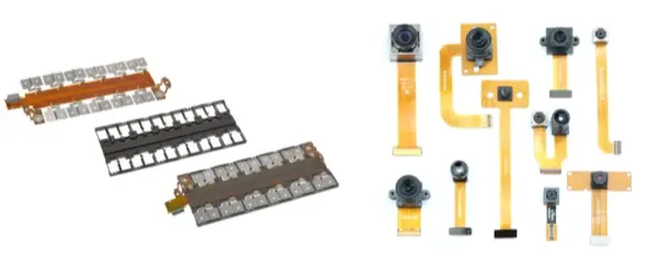
2. Ưu điểm và chi tiết về FPCs
So với các dây dẫn đồng, các bảng mạch in linh hoạt (FPC) có nhiều ưu điểm. Chúng có độ tích hợp cao, rất mỏng và cực kỳ linh hoạt. Những đặc tính này giúp cải thiện an toàn, giảm trọng lượng và bố trí gọn gàng. Ngoài ra, FPCs rất mỏng và có thể được thiết kế riêng để phù hợp với bộ pin. Trong quá trình lắp ráp, cánh tay robot có thể trực tiếp lấy và đặt chúng lên bộ pin. Điều này giúp tự động hóa dễ dàng hơn và hỗ trợ sản xuất hàng loạt. FPCs rõ ràng có xu hướng thay thế các dây dẫn đồng.
Ưu điểm và chi tiết:
Hiệu suất an toàn: FPC sử dụng lá kim loại để kết nối với thanh dẫn điện. Chúng có thể bao gồm thiết kế bảo vệ bằng cầu chì. Điều này đảm bảo các đường dẫn tín hiệu tốc độ cao. Nếu xảy ra chập điện, cầu chì của FPC sẽ tan chảy và ngắt đường dẫn. Điều này ngăn ngừa cháy nổ ở các phần khác của gói pin.
Nhẹ nhàng: So với các bộ dây dẫn và một số bảng mạch in (PCB) được sử dụng cho việc thu thập tín hiệu, các bảng mạch in dẻo (FPC) chiếm ít không gian hơn và có trọng lượng nhẹ hơn.
Độ linh hoạt trong quy trình: FPCs loại bỏ nhiều bước kết nối thủ công. Chúng cho phép hàn siêu âm, hàn chì và các quy trình khác. Về độ dày, diện tích mạch có thể là 0,34 mm và diện tích NTC là 2 mm. Chúng có thể uốn cong 90° hoặc 180°. Các tính năng này mang lại sự tự do thiết kế cao.
Sản xuất tự động: FPC có hình dạng đều đặn và độ tích hợp cao. Chúng giảm thiểu việc đi dây thủ công. Chúng phù hợp với sản xuất cơ khí quy mô lớn. Điều này giúp giảm đáng kể thời gian lắp ráp và lao động. Chúng hỗ trợ tự động hóa trong quá trình lắp ráp bộ pin.
Thị trường bo mạch in (PCB) trong ngành ô tô
1. Yếu tố thúc đẩy thị trường và các chứng nhận quan trọng
Trong những năm gần đây, sự phát triển của xe điện đã thúc đẩy sự tăng trưởng của ngành công nghiệp PCB. PCB là nền tảng cấu trúc cho các linh kiện điện tử. Chúng đóng vai trò quan trọng trong hệ thống điều khiển nguồn điện, điều khiển an toàn, điện tử thân xe và hệ thống giải trí thông tin.
Xe điện cần nhiều hệ thống điều khiển điện tử hơn so với xe chạy xăng truyền thống. Các xu hướng như điện khí hóa, trí tuệ nhân tạo và kết nối mạng đang làm tăng nhu cầu về bo mạch in (PCB) cao cấp cho ô tô. Nhu cầu này đòi hỏi các tiêu chuẩn độ tin cậy nghiêm ngặt. Thường thì các bo mạch in phải trải qua các bài kiểm tra kéo dài. Các bài kiểm tra có thể kéo dài từ một đến ba năm trước khi một linh kiện được nhà cung cấp chấp thuận.
Ngành công nghiệp điện tử ô tô có các tiêu chuẩn nghiêm ngặt đối với các sản phẩm dành cho ô tô. Các chứng nhận quan trọng bao gồm AEC-Q100, IPC-6011 và IATF 16949. Những tiêu chuẩn này nâng cao rào cản gia nhập và tạo ra một lợi thế kỹ thuật cho các nhà cung cấp PCB đủ điều kiện.
Thị trường PCB ô tô toàn cầu tiếp tục tăng trưởng. Việc áp dụng xe năng lượng mới là yếu tố chính thúc đẩy sự phát triển này. Với tư cách là nhà lãnh đạo toàn cầu trong lĩnh vực xe điện, Tesla sử dụng một lượng lớn PCB cho mỗi chiếc xe. Trong dòng xe Tesla Model, các bộ phận biến tần và Hệ thống Quản lý Pin (BMS) sử dụng nhiều PCB. Điều này làm tăng giá trị PCB cho mỗi chiếc xe.
Các xu hướng điện khí hóa và trí tuệ nhân tạo sẽ tiếp tục thúc đẩy thị trường. Khu vực Châu Á - Thái Bình Dương và Trung Quốc sẽ tiếp tục chứng kiến sự tăng trưởng mạnh mẽ. Các nhà sản xuất trong nước của Trung Quốc vẫn còn nhiều tiềm năng phát triển trên thị trường toàn cầu.
2. Các loại mạch in (PCB) trong ngành ô tô
Bo mạch in (PCB) trong ngành ô tô bao gồm các loại như bo mạch in nhiều lớp (multilayer PCB), bo mạch in linh hoạt (FPC), bo mạch in kết nối mật độ cao (HDI), bo mạch in tần số cao và các loại khác. Mỗi loại có vật liệu và ứng dụng khác nhau. Mỗi loại đóng vai trò riêng trong các tình huống khác nhau.
3. Dữ liệu thị trường và xu hướng
Số liệu và xu hướng thị trường (tổng hợp từ dữ liệu ngành):
Dự báo cho thấy thị trường PCB ô tô toàn cầu đạt $8,84 tỷ USD vào năm 2022. Dự kiến sẽ đạt $13,39 tỷ USD vào năm 2030. Tỷ lệ tăng trưởng hàng năm kép (CAGR) là 5,6%.
Trong khu vực Châu Á - Thái Bình Dương, thị trường đạt $4,42 tỷ USD vào năm 2021. Con số này tăng lên $4,83 tỷ USD vào năm 2022.
Sự tăng trưởng của xe năng lượng mới là yếu tố chính thúc đẩy nhu cầu về PCB. Năm 2019, giá trị PCB trên mỗi xe ô tô ước tính như sau: xe hạng thấp $30–40, xe hạng trung $50–70, xe hạng cao $100–150. Với xu hướng điện khí hóa và các yếu tố khác, giá trị PCB trên mỗi xe dự kiến sẽ tăng mạnh. Một dự báo cho thấy thị trường PCB ô tô toàn cầu sẽ đạt $12,48 tỷ USD vào năm 2028. Tỷ lệ tăng trưởng hàng năm kép (CAGR) từ năm 2020 đến 2028 ước tính khoảng 5,3%.
Một dự báo khác ước tính quy mô thị trường PCB cho xe năng lượng mới trên toàn cầu sẽ đạt 30,095 tỷ Nhân dân tệ vào năm 2025. Tỷ lệ tăng trưởng hàng năm kép (CAGR) của nó cao hơn nhiều so với xe sử dụng nhiên liệu truyền thống. Ngược lại, thị trường PCB cho xe sử dụng nhiên liệu truyền thống được dự báo sẽ giảm xuống khoảng 32,925 tỷ Nhân dân tệ vào năm 2025.
Nhu cầu về bảng mạch in (PCB) trong ngành ô tô tập trung chủ yếu vào các loại bảng mạch nhiều lớp và các khu vực cao cấp HDI. Cạnh tranh trên thị trường mạnh hơn ở phân khúc trung và thấp cấp.
Dữ liệu từ Jycircuitboard về thị phần của các loại bảng mạch in (PCB) trong thị trường ô tô cho thấy:
Bo mạch in (PCB) 1–2 lớp: 26.93%
Bo mạch in 4 lớp: 25.70%
Bo mạch in 6 lớp: 17.37%
Bo mạch in (PCB) 8–16 lớp: 3.49%
Bo mạch HDI: 9.56%
Bo mạch in linh hoạt (FPC): 14.57%
Vật liệu nền IC: 2.38%
Các con số này cho thấy bảng mạch đa lớp là nhu cầu chính trong điện tử ô tô. HDI và FPC đóng vai trò quan trọng trong các ứng dụng cao cấp.
Tóm tắt kết thúc
Bo mạch in (PCB) trong ngành ô tô phải đáp ứng các yêu cầu kỹ thuật nghiêm ngặt. Bạn phải lựa chọn vật liệu phù hợp. Bạn phải tuân thủ các quy tắc thiết kế chặt chẽ. Bạn phải sử dụng các bước sản xuất được kiểm soát và kiểm tra nghiêm ngặt. Bạn phải tập trung vào việc bố trí nguồn và đất, cũng như bố trí tín hiệu đúng cách. Bo mạch in dẻo (FPC) đang trở nên phổ biến hơn trong các hệ thống pin. Thị trường đang phát triển cùng với quá trình điện khí hóa và thông minh hóa xe hơi. Các bo mạch có độ tin cậy cao, nhiều lớp, HDI và FPC sẽ có nhu cầu mạnh mẽ. Các nhà sản xuất cần đáp ứng các tiêu chuẩn và chu kỳ kiểm tra. Việc này sẽ giúp các nhà cung cấp tham gia vào thị trường ô tô đang phát triển.