


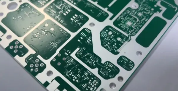
What Is a High-Frequency PCB
A high-frequency PCB is a special printed circuit board (PCB) used for high electromagnetic frequency signals. These boards are for radio frequencies above about 300 MHz (wavelength < 1 m) and for microwave frequencies above about 3 GHz (wavelength < 0.1 m). They are made on microwave base copper clad laminates. Production may use some standard rigid PCB steps or use special methods for these materials.

With fast progress in technology, more devices work in the microwave band (>1 GHz) and even in millimeter wave ranges (>30 GHz). This means frequencies rise and material needs increase. Base materials must have very good electrical properties and good chemical stability. As the signal frequency goes up, material loss must stay very low. With the arrival of 5G, high-frequency materials became more important.
Advantages of High-Frequency PCBs
1. High efficiency
Materials with low dielectric constant cause low loss. Modern induction heating and other methods can hit targets and keep high efficiency. These boards also help reduce waste and fit green goals.
2. High speed
Signal speed is inversely proportional to the square root of the dielectric constant. Lower dielectric constant means faster transmission. Special materials keep dielectric constant low and stable. This helps signal transfer.
3. Good control of heating or processing
High-frequency boards are used in many fields that need precise heating of metal parts. You can control how deep or where to heat. You can focus on surface or deep heating. You can heat in a focused or spread way. The board allows fine control.
4. Strong durability
Dielectric constant and dielectric material depend on environment. In humid areas, moisture hurts boards. High-frequency boards made from low water absorption material resist this. They resist chemical corrosion, moisture, high heat, and have high peel strength. These qualities make them strong in hard environments.
Common High-Frequency and High-Speed PCB Materials
| Brand / Maker | Typical Series / Types |
|---|---|
| Rogers | RO4003, RO3003, RO4350, RO5880 |
| TUC (Taiyao / TaYa or TUC brand) | TUC862, 872SLK, 883, 933 |
| Panasonic | Megtron 4, Megtron 6 |
| Isola | FR408HR, IS620, IS680 |
| Nelco | N4000-13, N4000-13EPSI |
| Domestic makers (China) | Dongguan Shengyi, Taizhou Wangling, Taixing Microwave |
(Use these example materials as a starting point. Each design needs the right material choice for frequency and layout.)
Difference Between High-Frequency Boards and HDI Boards
High-frequency PCBs are for radar, test instruments, automotive collision-avoidance systems, communication satellites, wireless systems, and other fields. HDI (High Density Interconnect) boards are for small devices with many components. HDI often uses double-sided boards in products with small volume.
A high-frequency board needs very high process control and precision. Many times designers start from FR-4 glass epoxy, but true high-frequency boards use special laminates. The board must have a small and stable dielectric constant, low dielectric loss, low water absorption, high temperature tolerance, and good corrosion resistance.
An HDI board uses micro blind vias to reach high routing density. It has internal and external routing that connect by drilling and plating. HDI is for compact products. Some HDI designs use modular parallel modules and strong DSP control for power and load features.
Types / Classification of High-Frequency Boards
Below are common types and notes about their processing:
1. Powder-filled thermoset (ceramic filled)
Materials and suppliers: Rogers 4350B / 4003C; Arlon 25N / 25FR; Taconic TLG series.
Processing: Steps are similar to FR-4 epoxy glass laminates. However, boards are brittle and easy to break. Tool life for drills and router bits drops about 20%. Handle with care.
2. PTFE (polytetrafluoroethylene, Teflon)
Materials and suppliers:
Rogers: RO3000 series, RT series, TMM series
Arlon: AD/AR series, IsoClad, CuClad series
Taconic: RF series, TLX series, TLY series
Taixing Microwave: F4B / F4BM / F4BK / TP-2B
Processing notes for PTFE:
Keep protective film when cutting raw sheets to avoid scratches and press marks.
Use new drills (standard #130 drills recommended). For best results, drill one sheet at a time. Keep clamp pressure at ~40 psi.
Use aluminum backstop and 1 mm melamine pads to hold PTFE during drilling.
After drilling, blow dust out of holes with hot air.
Use a stable drill machine. For small holes, increase speed and reduce chip load and spindle return speed.
Hole surface treatment: low-temperature plasma or sodium naphthalene activation help hole metallization.
PTH (plated through hole) copper deposition and adhesion need attention.
3. PTH copper deposition
After micro-etch (~20 microinch control), perform PTH. If needed, run a second PTH pass as required by board routing.
4. Solder mask (green mask) process
Pre-process: use acid/alkaline cleaning; avoid mechanical sanding.
After pre-process, bake the board (90°C for 30 min) and apply dry film.
Bake in three stages: 80°C, 100°C, 150°C, 30 min each. If mask shows oil spots, remove mask and repeat activation treatment.
5. Routing / milling PTFE boards
Use thin paper on PTFE trace side and clamp with FR-4 or phenolic backing during routing.
After routing, hand-finish edge burrs and inspect carefully. Avoid damaging copper and board surface. Use sulfur-free separation paper. Reduce burrs well. The routing step must leave good edge finish.
Production Flow for High-Frequency PTFE Boards
Below are three common process flows. I put them in a table for clarity.
| Process Type | Key Steps (summary) |
|---|---|
| NPTH (Non-Plated Through Hole) for PTFE | Cutting → Drilling → Dry film → Inspection → Etch → Etch inspection → Solder mask → Dry film exposure → Hot air solder leveling (HASL) or tin spray → Routing/shaping → Inspection → Final inspection → Packing → Delivery |
| PTH (Plated Through Hole) for PTFE | Cutting → Drilling → Hole treatment (low-temp plasma or sodium naphthalene activation) → Copper plating → Panel electrical test → Dry film → Inspection → Imaging → Etch → Etch inspection → Solder mask → Dry film exposure → HASL → Routing/shaping → Inspection → Final inspection → Packing → Delivery |
| Solder mask process controls | Control green mask adhesion and bubble formation carefully. |
Note: Each process step must control surface scratch and other defects strictly.
Applications of High-Frequency PCBs
High-frequency PCBs commonly appear in:
Power amplifiers and low noise amplifiers (LNA)
Mobile communication products and smart lighting systems
Power dividers, couplers, duplexers, filters and other passive devices
Automotive collision avoidance systems, communication satellites, wireless phone systems
In short, electronics are moving to higher frequencies and high-frequency boards follow this trend.
How to Design High-Frequency PCBs
In high-frequency PCB design, power plane layout is critical. Usually put power on its own layer. This helps the circuit follow the path of least impedance. Power plane must provide return paths for all signals on the PCB. That lowers loop area and reduces noise. Low-frequency designers often ignore some of these noise issues.
Follow these rules in high-frequency PCB design:
Keep power and ground stable and unified.
Careful routing and correct termination remove reflections.
Careful routing and correct termination reduce capacitance and measured crosstalk.
Below I expand several key subjects.
(1) Transmission line width
Transmission line width in high-frequency PCB design must follow impedance matching theory.
Impedance matching
When input/output impedance and transmission line impedance match, the system gives maximum output power and minimum reflection. For microwave circuits, matching must also consider device bias points. Vias on signal lines change transmission properties. For TTL and CMOS, characteristic impedance is high, so the effect is small. But for 50 Ω low-impedance RF lines, vias must be considered. Usually avoid vias on such lines.
(2) Crosstalk between parallel transmission lines
When two microstrip lines run close and parallel, coupling occurs. They cause crosstalk and change line characteristic impedance. Pay attention for 50 Ω and 75 Ω circuits. Designers can use coupling for some functions, such as directional couplers or power measurement. Example values from one design (1.97 GHz PCS end base station amplifier, dielectric εr = 3.48):
For a 10 dB directional coupler: S = 5 mil, l = 920 mil, W = 53 mil
For a 20 dB directional coupler: S = 35 mil, l = 920 mil, W = 62 mil
To reduce crosstalk, follow these rules:
A. Keep spacing S between high-frequency or high-speed parallel lines at least one line width.
B. Cut down parallel length where possible.
C. Keep tiny high-frequency signals away from power and logic lines that can cause strong interference.
(3) Ground via electromagnetic analysis
For IC ground pins or other ground pins, put ground vias close to pins in high-frequency circuits. The idea: a short ground path acts like an inductive impedance. Ground via also looks inductive. This affects filter function. That is why place ground vias close to pins. To reduce inductive load, use more ground vias than in low-frequency boards. This raises ground current capacity and helps keep all points near 0 V.
(4) Power filtering
For TTL and CMOS, designers add bypass capacitors near power pins to reduce logic noise. For high-frequency and microwave circuits, this is not enough. High-frequency signals make high-frequency interference on power. Use series inductors and capacitors. Choose inductors by working frequency. Example: to filter >1 MHz noise with C = 0.1 μF, pick L = 1 μH. When adding inductance on collector open-circuit signal pins, be careful. The inductor acts like a matching inductance then.
(5) Shielding
Use shielding to protect small or high-frequency signals. This reduces strong signal interference and reduces EMI. Some guidelines:
A. In low frequency digital/analog (<30 MHz) small-signal designs, split digital and analog grounds, and pour ground plane in small-signal zones. Keep distance between ground pour and traces greater than the trace width.
B. In high-frequency digital/analog small-signal design, add shielding cans or stitched ground vias to isolate areas.
C. For high-power high-frequency circuits, make the high-frequency part a separate functional module and add a metal shield box to lower radiation. For example, optical fiber transceiver modules at 155 M, 622 M, or 2 Gb/s.
A multi-layer PCB for mobile phone (example: Nokia 6110) may place components on both sides and use internal ground pours as shown in the original figure. (Figure references omitted here.)
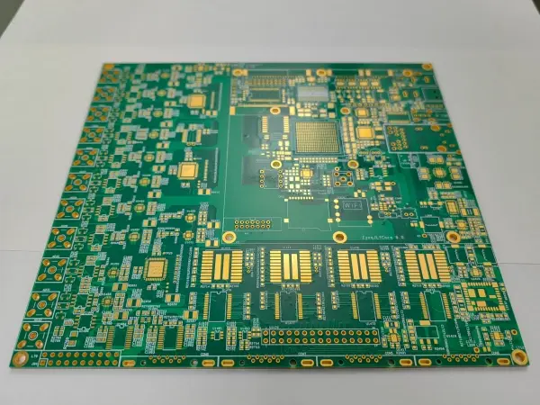
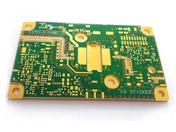
Examples of Material Selection for High Boards
Below are examples from boards we designed and debugged:
| Application (freq / device) | Material / Stack | Notes |
|---|---|---|
| 2.4 GHz spread spectrum relay | FR-4, 4-layer PCB with large ground pours | High-frequency analog part separated. Power lines use inductors to isolate from digital part. |
| 2.4 GHz RF transceiver | PTFE material, double-sided board | RF transmit and receive in separate metal shield cans; power input filtered. |
| 1.9 GHz RF transceiver | PTFE material, 4-layer PCB | Use large ground pours and shielding. |
| 140 MHz IF transceiver | Top layer S1139 0.3 mm | Large ground pour; via isolation. |
| 70 MHz IF transceiver | FR-4, 4-layer PCB | Large ground pour; module isolation via via fences. |
| 30 W power amplifier | RO4350 material, double-sided PCB | Large ground pour; spacing controlled to >= 50 Ω line width; shield box and power input filtering. |
| 2000 MHz microwave source | S1139 0.8 mm top | Double-sided PCB; precise control of trace dimensions. |
Use these as examples. Each project needs its own material and thickness choice.
High-Frequency PCB Material Requirements
Designers should check these key material properties:
Dielectric loss (Df, loss tangent) must be very small. Small loss means less signal attenuation.
Low water absorption is important. High water uptake changes dielectric constant and loss.
Dielectric constant (DK) must be low and stable. Lower DK gives higher signal speed. DK stability also helps impedance control.
CTE and thermal match between copper foil and base must be similar. Large mismatch over temperature changes can cause copper delamination.
High frequency often means use of fluoropolymer substrates like PTFE (known as Teflon).
Manufacturing Notes and Cautions for High-Frequency PCBs
Impedance control is strict. Line width tolerance is tight. Typical control tolerance ~ ±2%.
PTH adhesion is low on special materials. Use plasma surface roughening for holes and surfaces to increase adhesion for plating and solder resist.
Do not sand the board before soldering. This reduces adhesion. Use micro-etch solutions or other roughening methods only.
PTFE boards often cause rough edges with standard milling tools. Use special milling bits and follow PTFE routing practices.
Short Conclusion
High-frequency PCBs need special materials and careful process control. Choose a material that fits your frequency and thermal needs. Control impedance and place ground vias closely. Use shielding and correct power filtering. Follow special handling steps for PTFE and other microwave laminates. These steps improve performance and yield in high-frequency circuits.