We went to a PCB shop and asked them: “Can you control trace impedance to within 10%?” They would answer you with full confidence: “No problem!” If you push a bit and ask for 8%, they might think for a moment and then say: “Okay (for inner layers)!” If you ask then: “Can a via be controlled to 10%?” the little boat of friendship might… flip!
The Core Question: Traces vs. Vias Impedance Tolerance
Both traces and vias link transceiver chips. So why can traces be held to 10% while vias cannot? We know traces are not easy to control either. Factors that affect trace impedance include etch factor, layer shift, and surface roughness. For microstrip lines, soldermask and copper thickness also matter. Still, many mainstream board shops can guarantee 10% or even 8% impedance tolerance for traces. For vias, from what I know of board shops, none promise to control via impedance within 10%. That means there are many factors for vias that board shops cannot control, so they cannot guarantee it.
What This Article Covers
In this article, I first introduce two via processes: drilling and via filling. Many people know drilling matters, but how much does drilling tolerance affect via performance? For filling, many think filling a via with resin or soldermask will change via performance. We test these effects with simulation.
1. Drilling Process and Its Impact on Via Performance
First, drilling. We often hear two names: drill size and finished hole size. If we design an 8 mil hole in our PCB file, do you think the factory will use an 8 mil drill bit? Of course not. A via must connect traces on different layers. The hole must be plated so copper runs vertically through the hole. That is plated-through copper. According to the IPC standard, plated-through copper thickness has set requirements, about 18 µm to 20 µm. So factories guarantee the hole is 8 mil after plating. That final size is the finished hole. That means the original drill size must be larger than 8 mil. How much larger? 10 mil? 12 mil? This size difference has a big effect on via performance.
According to factory drill tolerance rules, a 0.2 mm (8 mil) finished hole will use at least a 0.25 mm (10 mil) drill bit. If you do not specify tighter control, the factory might use a 0.3 mm (12 mil) drill bit. Everyone knows that a larger drill makes lower impedance. But how much lower? Our simulation results can show you.
The simulation shows that vias from 0.2 mm to 0.3 mm have an impedance difference of more than 5 ohms.
If we look at losses caused by the via, we can also see clear differences.
For this single via drilling process, the machining tolerance alone can cause more than a 10% swing.
2. Via Filling: Simulation and Results
Now about via filling. Many friends asked whether filling a via affects via performance. I kept telling them: “No effect! No effect!” They believed me, but still had some doubts. So I ran simulations to check.
The picture below shows the models for unfilled and filled vias. Red means resin or soldermask filling the via.
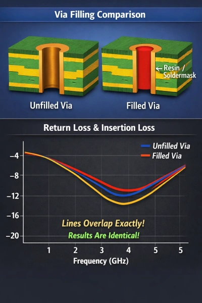
We compared return loss and insertion loss for the two cases. Why is there only one line? Because the lines overlap. Why do they overlap? Because there is no effect. The results are the same.
Theoretical Reason: Why Filling Does Not Matter
Anyone with some high-speed theory knows that at higher speed the signal shows skin effect. The signal flows near the via outer wall. So no matter what dielectric is inside the via, the electromagnetic field between signal and reference does not wrap into the inside. If there is no field inside, then the material inside the via will not have any effect.