
SMT Assembly
Services
From solder paste to populated boards.
FLJ PCB connects solder-paste printing, component placement, reflow and inspection for your surface-mount build. We support single- and double-sided boards, fine-pitch packages and mixed-technology assemblies, with PCB fabrication, component sourcing, programming and testing available around the assembly.
Engineering samples · Small runs · Production assemblies
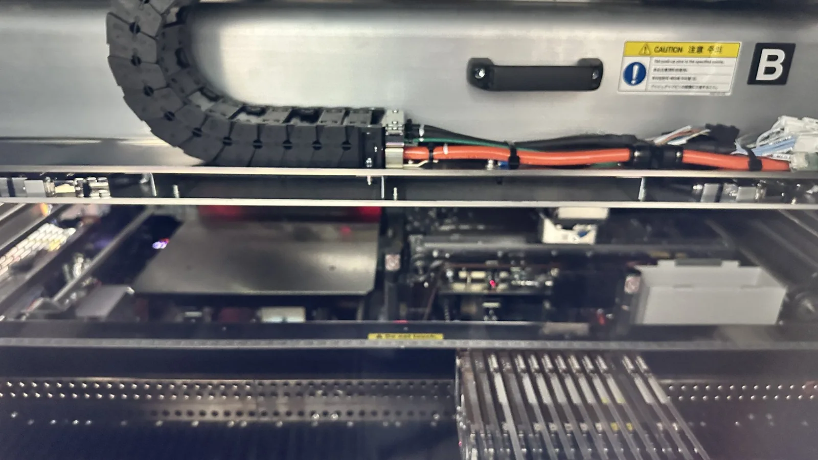
7 SMT linesManufacturing resources
Yamaha YRM20Component placement
SPI · AOI · X-rayComplementary inspection
Explore the assembly equipmentSurface Mount Assembly for Your PCB Design
SMT mounts surface-mount devices directly onto the board’s pads. It lets designers use compact components and both board surfaces, while the manufacturing process connects those components into the intended assembly.
Compact, component-dense boards
We prepare the printing, placement and soldering work around your pad geometry and component mix. Small passives and closely spaced IC connections need a coordinated process, so a dense design is considered as a complete assembly.
Single- and double-sided designs
Our team plans the board handling and assembly sequence for one or both surfaces. Component clearance, board support and the work on each side are connected before the board moves through manufacturing.
Boards with a mixed component set
Surface-mount circuitry can share a board with leaded connectors and other inserted parts. FLJ combines SMT with through-hole and manual soldering resources to complete the work your product needs.
For engineering evaluation, explore prototype PCB assembly. For ongoing small production batches, see low-volume PCB assembly. This page focuses on the surface-mount manufacturing work used within those builds.
SMT Assembly Capabilities
FLJ supports single- and double-sided surface-mount assembly, including BGA, QFN, QFP and other IC packages. Our engineering team connects the board, component information and manufacturing resources to prepare the build.
| Assembly detail | Published reference | How we apply it |
|---|---|---|
| SMT board size | Up to 310 × 410 mm | Review the board outline with the proposed panel, handling and support. Panel and carrier dimensions are considered separately. |
| Board thickness | 0.5–3.0 mm | Connect the board construction with clamping, support and the selected soldering route. |
| Small passive components | 0201 imperial, nominally 0.6 × 0.3 mm | Match the actual part designation and land pattern with stencil and placement preparation. |
| Leaded component pitch reference | 0.3 mm | Review terminal geometry, pad spacing, paste deposition and inspection access. |
| BGA pitch reference | 0.3 mm | Review the package, land pattern, solder materials and hidden-joint inspection together. |
| Assembly configuration | Single-sided, double-sided and mixed technology | Plan the work on each surface and the through-hole or manual steps needed to complete the assembly. |
| Process and inspection | Automatic printing, placement, reflow, SPI, AOI and X-ray | Prepare the manufacturing settings and checks around the board’s component and connection risks. |
These published SMT references guide the initial review. The feasible combination of board, panel, package and tooling details is reviewed for your design; individual limits do not describe every possible combination. Equipment positioning specifications are separate from the finished assembly’s acceptance requirements.
From Solder Paste to Populated Boards
The work before placement is as important as placing the parts. FLJ links the manufacturing information, material preparation and process checks so each stage prepares the board for the next.
- 01
Engineering and material preparation
We review the board files, BOM, placement information and assembly drawings for the selected configuration. Component identity, polarity and unpopulated positions are connected with the program and material kit. Moisture-sensitive parts are handled with their packaging, exposure history and applicable supplier instructions in view. Panel features, fiducials and support are considered alongside the design.
- 02
Stencil printing and solder-paste inspection
The stencil defines where paste is deposited. Aperture geometry, foil thickness and the paste influence the amount deposited and how it releases onto the pads. This matters where fine-pitch terminals and larger solder areas share one board.
3D SPI examines deposit characteristics before placement, including position, area, height and volume. Findings at this stage can feed back to the print setup while the deposits are still accessible.
- 03
Component identification and placement
Placement preparation connects the actual component, feeder or tray, footprint data, location and rotation. The machine uses board reference features to position the components on the printed deposits. Initial assembly checks help identify a configuration or orientation problem before it repeats across the run.
- 04
Reflow soldering
Reflow heats the assembly so the solder alloy melts, wets the intended surfaces and forms joints as it cools. We prepare the thermal process around the solder materials, component requirements and board construction. The process must account for areas that heat differently across the assembly.
The oven setting alone does not describe the temperature at every joint or component. Board population and thermal mass help determine the process preparation needed for the actual build.
- 05
Inspection and manufacturing completion
AOI reviews visible assembly features, while X-ray supports selected hidden-joint inspection. Relevant findings are connected with a correction and recheck. Through-hole work, programming and product-specific electrical or functional tests can then be included to prepare the agreed delivered assembly.
Double-Sided and Fine-Pitch Assembly Support
A more demanding assembly needs the board, packages and process to be considered together. Our engineers connect those details with practical handling, soldering and inspection.
Plan both surfaces as one build
A double-sided assembly exposes the board to more than one soldering operation. FLJ reviews the component arrangement, permitted thermal history and board support when planning the sequence. Parts already fitted on the first side must also be considered during the second-side work.
Give fine-pitch connections a matched process
Small pads and closely spaced terminals connect stencil preparation, paste deposition, positioning and soldering. We review those features together instead of treating placement accuracy as the whole manufacturing result.
Include hidden joints in the inspection route
BGA and other bottom-terminated packages can conceal connections from direct optical inspection. Our team connects package information and process preparation with the X-ray and further verification relevant to the build.
Inspection That Supports SMT Quality
Inspection gives useful feedback when it is connected to the process stage and the feature being checked. FLJ combines paste, assembly and hidden-joint inspection with the product’s selected verification.

Review the printed deposits
SPI can identify an unsuitable deposit before the component is added. The finding can guide a check of print alignment, stencil condition or the deposit setup.
Inspect the populated board
AOI reviews visible component and solder features against its programmed criteria. X-ray provides another view for selected connections that the package hides from optical inspection.
Connect the checks with the required function
Programming, ICT and functional tests can be included around the firmware, access and expected responses of the product. These activities complement assembly inspection and are defined in the quoted scope.
Use findings to improve the relevant stage
A print issue, a placement mismatch and a soldering issue call for different investigations. We compare the observed condition with the build information and process stage, then review the relevant correction and recheck. This helps keep the response focused on the manufacturing work involved.
Match residue handling to the materials and use
Flux type, the soldering process and later finishing affect residue handling. Where cleaning or coating is part of the project, we review the material guidance and required delivered condition. The no-clean label alone does not establish compatibility with every later material or application.
Connect SMT with the Rest of Your Build
Choose the manufacturing support that fits the boards, materials and resources you already have. FLJ can connect the surface-mount work with the steps needed to deliver your PCBA.
PCB fabrication and component sourcing
Turnkey assembly brings board fabrication and component purchasing into the build. Partial-turnkey and customer-supplied arrangements let you provide selected materials while we coordinate the remaining work.
Compare supply arrangementsThrough-hole and manual assembly
DIP, wave-soldering and manual resources support connectors and other parts that need additional operations. The component mix and access guide the sequence and any useful tooling.
Review mixed-assembly supportProgramming and product-specific tests
Offline or in-circuit programming can be combined with the selected checks and functional procedure. This connects the physical assembly with the firmware and operating conditions needed for its next integration step.
Explore programming and verificationWhy Choose FLJ PCB for SMT Assembly?
Work with one manufacturer across the board, materials and assembly.
FLJ PCB is the manufacturing brand of Shenzhen Philifast Electron Co., Ltd. Our engineering, purchasing and production support connects manufacturing questions with the actual work needed for your project.
Meet FLJ PCBPlacement and soldering resources
Seven SMT lines with Yamaha YRM20 placement equipment support surface-mount work. Two DIP lines and two manual soldering lines extend the route for mixed assemblies.
Inspection connected to the process
Automatic printing, 3D SPI, AOI and X-ray support manufacturing preparation and inspection at different stages. Programming and product-specific test work can be planned with the assembly.
Engineering support through the build
File and component questions can be reviewed alongside board handling, soldering and verification. This keeps the preparation connected rather than leaving your team to coordinate separate manufacturing stages.
See the assembly resourcesSMT Assembly Cost and Lead-Time Planning
A useful quotation connects the board design and quantity with the preparation and delivered condition. Our team reviews those details together so the price and schedule describe the work you need.
What contributes to the assembly quotation
Component types and placement work, the number of populated surfaces, stencil and machine setup, feeder preparation and board support all affect the SMT scope. Through-hole operations, manual work, programming and the selected tests add their own preparation and execution.
For a repeat build, we can review whether existing tooling and programs still suit the current design. A changed footprint, component mix or inspection need may alter that preparation.
What sets the manufacturing schedule
PCB and component availability, tooling, engineering questions and test preparation can influence the delivery date alongside the time on the assembly line. An available material kit and a ready manufacturing package help the team plan the production work.
If your build has a fixed deadline, share it with the available files. We can discuss the schedule around the actual supply and preparation, including the options relevant to an urgent build.
Quick-turn assembly planningRequest an SMT Assembly Quote
Send your board files, BOM and intended quantity. Tell us what you want the completed assembly to include.
Placement information, assembly drawings and known programming or test needs help us review the complete build. You can identify any boards or components you will supply and share your desired delivery.
If the package is still developing, send the information you have. Our team will follow up on the details needed for the quotation and production preparation.
Assembly file guideSMT assembly questions
What is the difference between SMT, SMD, PCB and PCBA?
SMT is the surface-mount assembly process. An SMD is a component designed for surface mounting. A PCB is the circuit board that carries the connections; a PCBA is the populated board after components have been assembled. The services around that assembly, such as sourcing and testing, follow the project scope.
Can FLJ assemble both sides and include through-hole parts?
Yes. We review the work on both surfaces and the leaded components to plan a suitable mixed-technology route, including the relevant support, soldering and inspection.
Can we supply our own PCBs or selected components?
Yes. Customer-supplied and partial-turnkey arrangements can form part of the build. Identify the materials you plan to provide so we can connect their preparation with the rest of the assembly.
Can I start an enquiry without every manufacturing file ready?
Yes. Share your existing board files, BOM and questions. Our engineers can review the starting information and explain what else is needed for the quotation and manufacturing preparation.
Technical background
The process explanations use TI’s QFN and SON board-mounting guidance, NXP’s retained surface-mount reflow reference, and Indium’s residue and coating compatibility discussion. Component- and material-specific instructions guide the actual process; these references do not establish additional FLJ capabilities.