
Flexible PCB Manufacturing
Flexible circuits. Precisely made for the space they connect.
Custom polyimide circuits with the copper, coverlay, contact finish and local reinforcement your design needs. Single-sided, double-sided and multilayer builds, from prototypes to production.
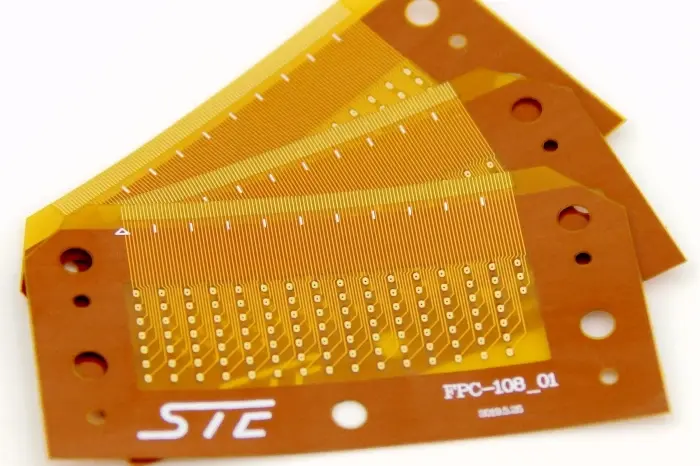
- Circuit types
- Single-sided · double-sided · multilayer
- Local features
- Coverlay · contact ends · reinforcement
- Supply
- Bare circuits · optional assembly
Flexible Circuits for Compact and Moving Assemblies
A flexible circuit carries patterned conductors on a thin insulating film. Its outline can connect parts that sit on different planes, follow a narrow enclosure or reach a connector away from the main electronics. The circuit combines the connection route and the conductor pattern in one manufactured part.
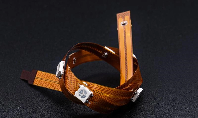
Flex to install
A flex-to-install circuit is formed during assembly and then held in position. This can connect a display to its controller, link a sensor to another board or carry signals around a mechanical feature. End support and the installed path help keep the bend where the product intends it to remain.
The choice includes more than the flat outline: clearance around the formed circuit, connector orientation and the transition out of a reinforced area all affect how the part fits. The flexible body can remain thin while selected ends provide the thickness and support needed for connection.
Flex in motion
A dynamically flexing circuit moves during normal operation, such as within a moving sensor assembly or a mechanism with a repeated travel path. That repeated deformation makes the copper foil, conductor arrangement, total flexible thickness and bend geometry part of the same selection.
The motion path defines the bend geometry, travel and support conditions. Those conditions, together with the environment, guide material selection and mechanical evaluation for the completed circuit. The finished part must carry its electrical connections through that intended movement.
Flexible Circuit Types and Material Options
Choose the circuit construction
| Circuit | What it provides |
|---|---|
| Single-sided | Single-sided flex uses one conductive layer and is useful when the required connections can be routed on one side of the film. Exposed termination areas and local reinforcement can be included where the part connects to the rest of the product. |
| Double-sided | Double-sided flex provides copper patterns on both sides, with plated connections where the design joins them. It creates additional routing choices around pads and contact ends. The copper and protective layers on each side contribute to the finished flexible thickness. |
| Multilayer | Multilayer flex adds routing and reference resources for more involved circuits. Bonding materials, internal connections and the way the layers are held together also affect mechanical behavior. More copper layers provide circuit resources; they do not automatically preserve the flexibility of a simpler construction. |
Polyimide, copper and the bond between them
Polyimide film provides the flexible insulating base for many soldered electronic circuits. An adhesive-based laminate includes a bonding layer between the film and copper. An adhesiveless laminate forms that base without a separate adhesive layer at the copper-to-film interface. Other bonds in the completed circuit, including coverlay and stiffener bonds, can still be present.
Rolled-annealed and suitable electrodeposited copper foils offer different material and processing characteristics. For repeated movement, foil ductility and thickness are considered with the completed layup and the conductor path through the bending region. Local changes in geometry can concentrate strain, so the material and the routed shape work together.
Copper thickness also affects conductor geometry, current carrying requirements and bending behavior. Polyimide, copper, coverlay and the relevant adhesive layers together form the flexible section; a starting film thickness is only one part of its finished build.

Protection and surface options
Film coverlay covers the circuit while leaving openings for pads, contacts and other exposed features. Its film and adhesive contribute to the structure and to behavior during bending. Suitable flexible photoimageable coatings can serve applications with different opening and process requirements.
Surface finishes protect the exposed conductor and prepare it for soldering or contact. ENIG and other appropriate finishes are selected according to the termination and assembly route. The surface finish, coverlay and local stiffener each perform a different job.
Coverlay, Contact Ends and Local Reinforcement

Keep the connection surface exposed
A contact end needs the intended conductor area available to the mating connector. The coverlay opening, contact pattern, outline and insertion direction describe that region together. The exposed surface is finished for its connection function.
Solder lands need a surface suited to the assembly process. Mating contacts also depend on the connector interface and expected contact use; where a specified gold-plating system is required, its type and thickness form part of the termination specification. Coverlay protects the adjacent circuit while keeping those connection surfaces accessible.
Match the finished contact-end thickness
A connector accepts a defined finished thickness at the inserted portion of the circuit. That local thickness can differ from the ordinary flexible body because coverlay is opened there, copper may differ between sides and reinforcement may be added.
The contact-end build includes the layers actually present at that location: conductor and finish, insulating film, any retained copper or protective layers, and the selected bond and stiffener. Adhesive thickness after bonding contributes to the result. The connector’s nominal thickness and tolerance define the finished target. Local layer thicknesses and the bonded adhesive are selected together so the completed end fits that window.
Some ends need a PI stiffener to reach the required local thickness and support. Other constructions may already provide the specified end geometry. Contact-side orientation and the local stack establish where any reinforcement belongs.

Add support where the part needs it
PI, FR-4 and suitable metal stiffeners offer different ways to support a connection or mounting area. PI can add local thickness at an insertion end; a more rigid reinforcement can support a component region, a mounting feature or a handling area. An appropriate adhesive joins that support to the flexible circuit.
The reinforcement boundary also changes where bending occurs. Its position is selected with the connection end and the free flexing region, so the circuit leaves the supported area along its intended path. A stiffener adds mechanical support; it is different from a rigid-flex section containing its own routed rigid layers.
Pressure-sensitive adhesive can provide a separate mounting function where the circuit is fixed to another surface. Its location and any release liner are defined with the outline and the areas that remain free to move.
Fabricating and Delivering the Flexible Circuit
From thin laminate to the finished outline
FLJ forms the circuit patterns on the selected flexible laminate and creates the specified interlayer connections. Handling and registration keep the thin material positioned through imaging and subsequent processing. The required openings and alignment features carry that positioning into the coverlay operation.
Coverlay is prepared and bonded over the circuit with the termination areas left accessible. Appropriate surface finishing, stiffener bonding and adhesive application complete the local features in the fabrication plan. Profiling then gives the circuit its finished shape, whether the part is a simple tail, a branched interconnect or a shaped connection within an enclosure.
Check the features that connect and fit
FLJ checks the conductor features and protective-layer openings, then verifies the local features that locate the circuit in the product: contact-end width and length, reinforcement position and the finished outline. Local thickness measurements address reinforced or mating regions where their dimensions differ from the flexible body. Electrical testing checks the required connections and isolation against the circuit data.
For a design that operates in motion, mechanical validation is matched to the actual construction, bend geometry, travel and environment. Initial electrical continuity and a successful connector fit answer different questions from repeated-flex performance.
Prototypes, production and delivery
Prototype parts support checks of the formed path, connector fit, mounting and the intended assembly. Production carries forward the selected materials, circuit and coverlay artwork, reinforcement definition and fabrication requirements.
Parts can be supplied in an appropriate panel or individual format, with handling and packaging suited to their shape and contact surfaces. Protecting the circuit from unintended creases and keeping the contact and adhesive areas in the intended condition support the next assembly operation.