
Custom Cable & Wire Harness Assembly
FLJ PCB builds custom cable assemblies and wire harnesses that connect defined endpoints in your product. The work brings together the specified wire, contacts, connector housings, branch positions and protective materials.
Cable assemblies can be supplied separately or coordinated with your PCB assembly and enclosure integration.
Start with the connection you need to make.
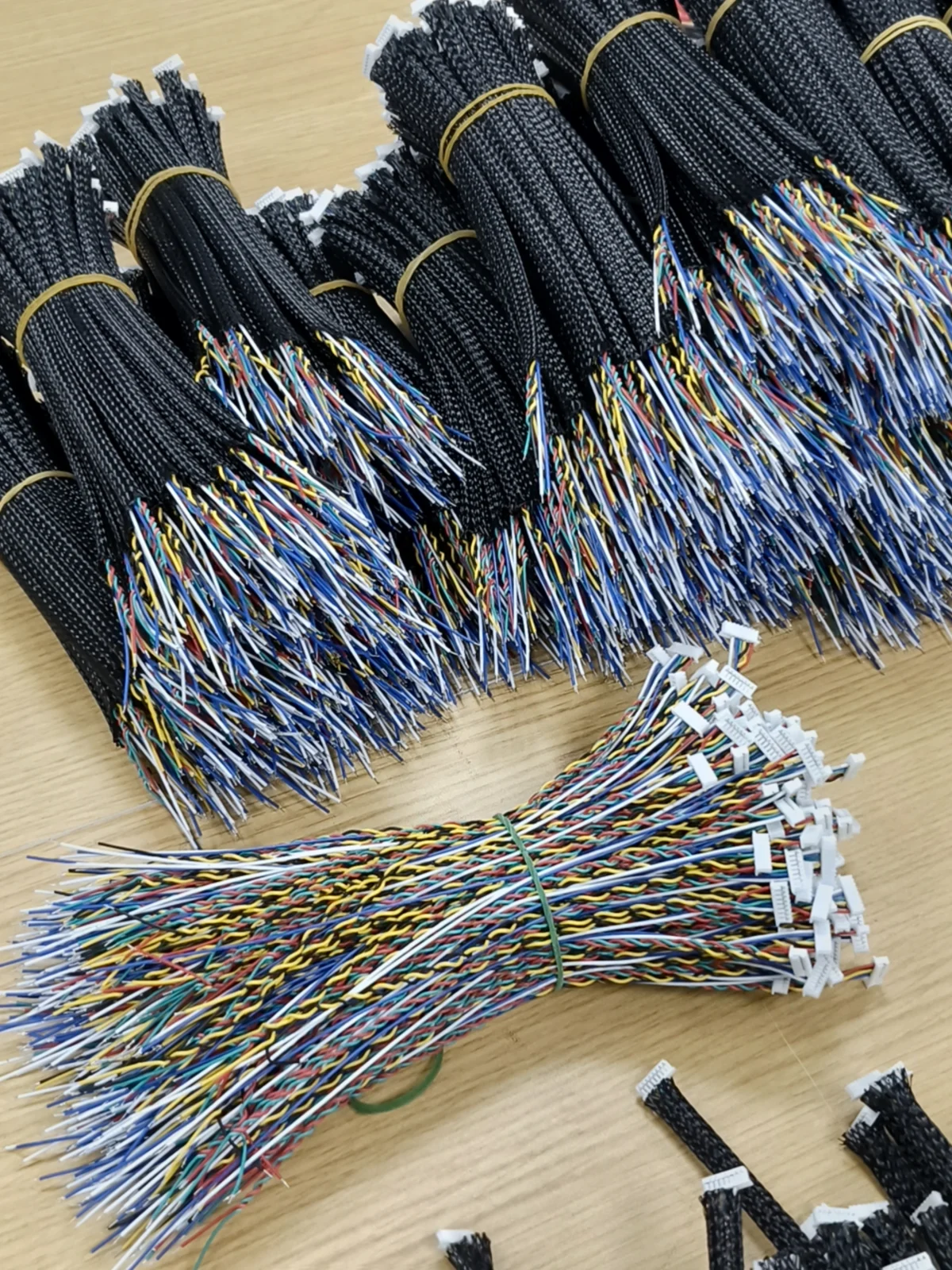
Cable Endpoints and Harness Form
A cable assembly links defined endpoints. A wire harness organizes several wires into a routed assembly, often with branches, identification and protective sleeving. Their physical form follows the connectors and installation space in the product.
FLJ’s published cable range includes industrial wiring, USB and Type-C, SAS and display-interface cables. Builds can carry internal power and signals, connect boards, or terminate at an external interface. The selected connector family and wiring arrangement define the supplied assembly.
- Internal wiring
- Wire lengths, branch positions, terminal housings and identification for the connections inside your product.
- Cable-to-board connections
- Mating parts, cavity assignments and cable exits coordinated with the assembled PCB.
- Interface cables
- Connector ends, shielding and cable construction reviewed for the intended power or signal application.
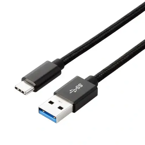
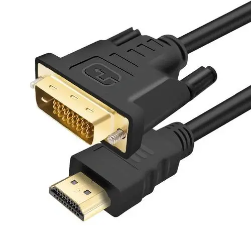
Wire Preparation, Contacts and Terminations
Wire preparation exposes the conductor needed for the selected termination while preserving the surrounding insulation. FLJ’s cable work can use crimp contacts, soldered connections or another termination specified for the connector.
A crimp joint is made by a matched combination of wire, terminal and tooling. The conductor crimp forms the electrical joint; the insulation crimp, where present, supports the insulated wire. Equal conductor sizes can have different insulation diameters, so both fit conditions matter. Strip length and tool settings follow the terminal’s application information.
Technical reference: TE Connectivity, Premium Manual Hand Tools Catalog, wire/terminal/tool selection discussion, printed pages 2–3.
Exposed strands, insulation position and contact condition are checked during preparation and assembly. A bent terminal can interfere with housing insertion, retention or mating even if the conductor is electrically connected. Sleeving, heat-shrink, ties and labels complete the harness arrangement shown in the drawing.
Routing and Support at the PCBA Interface
The board connector and mating cable end share a physical interface: pin assignments, keying, cable exit direction and connector access. FLJ coordinates those details with the PCB assembly when the cable belongs to the same build.
A correct electrical map does not guarantee an installable route. A branch point placed too close to the board can obstruct mating, while a cable exit can block a mounting screw. Installed length and support are checked against the surrounding geometry.
The cable drawing, wire list and identification follow the selected board and connector revision. A change on either side of the interface is checked for its effect on the other. Enclosure installation and complete-unit integration are covered by Box Build Assembly.
Pin Mapping, Retention and Electrical Checks
Endpoint testing compares the required electrical map and detects missing or unintended connections. Workmanship, retention and dimensional checks establish separate features of the finished harness.
| Check | What it establishes |
|---|---|
| Connection mapping and opens/shorts | Expected electrical paths are present; missing or unintended connections are detected against the agreed reference. |
| Workmanship and retention | Termination condition, insulation position, contact seating and the specified mechanical support are checked. |
| Dimensions and fit | Lengths, branch locations, connector orientation and routing are checked against the drawing or fit reference. |
Continuity alone does not establish contact retention or high-speed signal behavior. Pull tests, insulation resistance, dielectric withstand and application-specific signal checks use their own methods, limits and agreed sampling. Destructive tests follow the selected sample plan.
Where IPC/WHMA-A-620 or another acceptance reference is specified, its applicable requirements are included in the build. Broader board-level methods and documentation are covered on PCB Testing and Acceptance & Traceability.
The Drawing, Pin List or Sample Reference
A wiring diagram, pin list, connector part numbers or an existing sample can define the connection. For a sample-led project, the reproduced features and any unresolved details are identified before the sample becomes the build reference.
The build reference brings together wire type and size, terminals and connector housings, overall and branch lengths, shielding, labels and protective materials. Length measurement points matter: a cable should reach its mating position without loading the contact or forcing the wire into place.
Pin assignments use an explicit view and cavity numbering. The mating face and wire-entry face show opposite sides of a connector; recording the view prevents a correct pin list from becoming a mirrored assembly.
| End A | Connection | End B |
|---|---|---|
A.1 | Power | B.3 |
A.2 | Return | B.1 |
A.3 | Control | B.2 |
Arbitrary example identifiers, not a connector face drawing. Actual cavity numbering follows the selected connector’s documentation.
The first assembly checks the specified connection against the intended fit and route. Agreed changes to branch position, length or identification then become part of the reference for repeat builds.
Send Your Cable or Harness Requirement
Send a drawing, pin list, connector information or sample details, with quantity and target timing. Identify the endpoints to connect and whether the harness is supplied separately or fitted with your PCBA.
If the drawing is still developing, start with the connection and installation space. The quotation can identify the remaining connector, wire, length or test information needed for the assembly.