
PCB Reverse Engineering Services
Recover missing design information and develop a manufacturable replacement for an existing board.
FLJ reconstructs PCB data, schematics and bills of materials from available boards and records. We connect the recovered design with approved component changes, prototype fabrication, assembly and defined verification, according to the work your project needs.
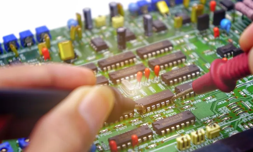
PCB Reverse Engineering Capabilities and Technical Approach
FLJ rebuilds the information needed to understand and reproduce an existing PCB: component identities, pin connections, the schematic, BOM and physical board data. The investigation relates each recovered item to the sample or available records, with unresolved parts and damaged connections identified for follow-up.
- Reconstruct the design
- Component and connection mapping, schematic and BOM recovery, PCB layout and manufacturing data.
- Develop a replacement
- Approved part alternatives and engineering changes around the required mechanical and electrical interfaces.
- Build and verify
- Prototype fabrication and assembly, specified programming, debugging and product-specific checks.
Component Identification and Circuit Reconstruction
We record each component’s reference designator, visible marking, orientation, package outline and polarity. Manufacturer marking information, package drawings and pin data help identify candidates. We then match the device pins to the actual pads and surrounding circuitry; a familiar package alone does not establish its pinout. Unconfirmed identities remain identified as open items in the parts list.
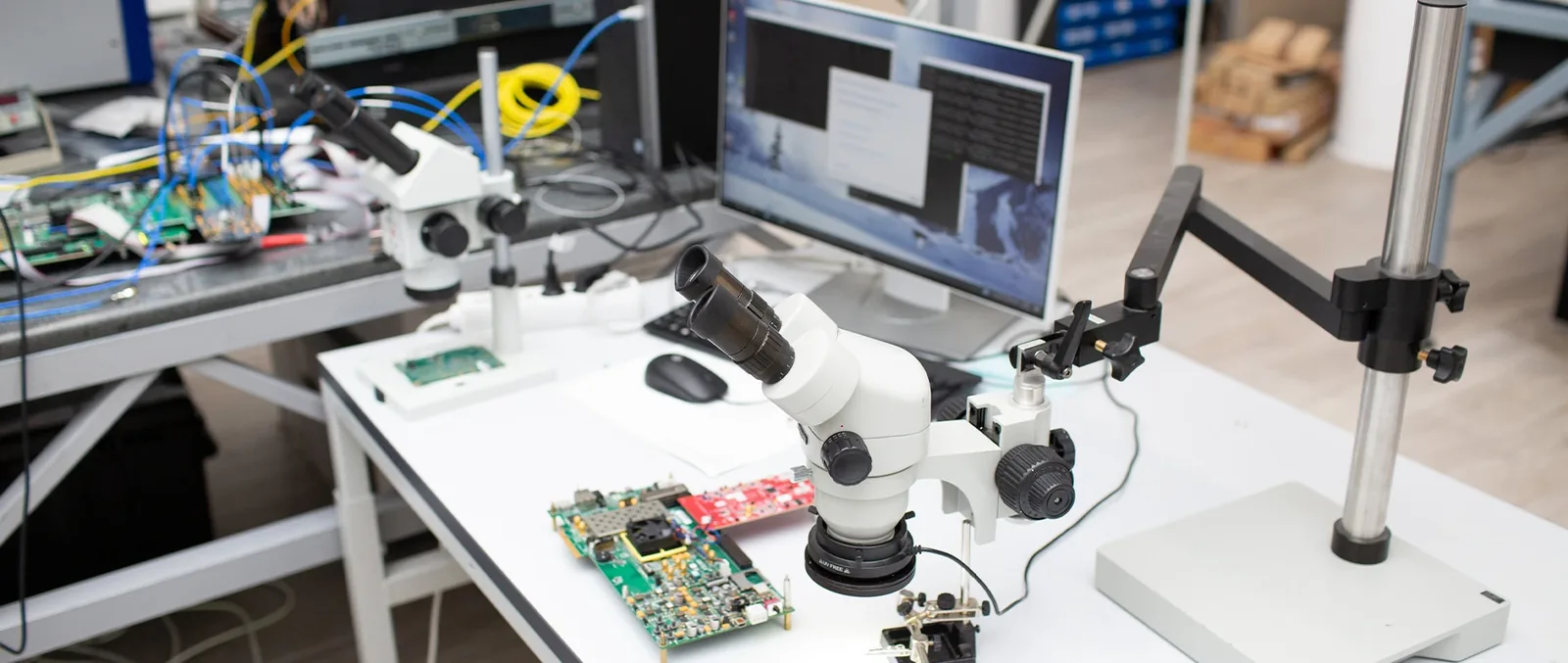
On the unpowered board, resistance and continuity measurements support pin-to-pin investigation. A continuity indication depends on the meter’s threshold and the probe contacts; a brief response can also result from a capacitor charging. Resistance measured across a fitted component can include parallel circuit paths. We compare these observations with the markings and connections, isolating a measurement where necessary within the permitted sample handling.
We organize established pin-to-pin relationships into nets and functional groups, then reconstruct the schematic and associated BOM. The netlist describes which pins connect. The PCB data must additionally preserve or define the route, copper planes and physical placement shown in the geometry example below.
PCB Geometry and Multilayer Connection Recovery
We reconstruct the board outline, mounting holes, connector positions, copper features, plane areas and vias. These features control physical fit and the copper path, so an endpoint connection list cannot replace their geometry. For a replacement board, connector alignment and component heights also need to fit the product’s mechanical arrangement.
For multilayer boards, layer images and node-to-node measurements supply different information. Images of the relevant layers retain copper shapes; connectivity measurements alone do not reveal hidden trace routes or plane boundaries. We identify which geometry is observed and which still requires investigation. Any component removal, coating removal or layer exposure needed to obtain that evidence is addressed in the sample-handling scope before work.
Existing Gerber or other manufacturing data can support reconstruction, but layers must be assigned to the physical stack and drill data to the correct hole spans. A wrong blind- or buried-via span changes the extracted connections. Creating an editable PCB also requires rebuilding missing component definitions and checking pads, holes and copper objects; manufacturing artwork does not retain all the information in the original design project.
Our PCB Reverse Engineering Process
We define the recovery goal and sample conditions, then agree which design records and prototype work the project needs. Each stage produces a reviewable file, decision, or result.
-
Define the recovery goal
We establish the board’s role, sample condition, existing records, required quantities and intended use of the recovered data or replacement board.
ResultA project target, known information gaps, and materials for assessment.
-
Set the scope and quotation
We select the investigation approach and define permitted sample treatment, required files, any changes, prototype work and acceptance criteria.
ResultAn agreed scope, deliverables, review points, and quotation.
- Document the board and map connections
We photograph the sample, identify components and orientation, investigate pin connections, and record board geometry and hidden-layer questions.
ResultA component and connection record linked to the sample, with unresolved findings.
-
Reconstruct the design records
Within scope, we develop the requested schematic, bill of materials (BOM), and PCB data, flagging unresolved parts or connections.
ResultDraft files and a list of open questions or assumptions.
-
Review and approve engineering changes
For obsolete parts or requested changes, we explain effects on related records and proceed with the changed configuration after approval.
ResultThe selected parts and design changes identified in an approved revision.
-
Build and check a prototype if selected
For FLJ-built prototypes, we fabricate and assemble the approved design, add specified programming, and perform the included checks using the required operating information.
ResultA prototype and recorded results for the checks performed on that configuration.
-
Release the agreed deliverables
We package scoped design files, BOM, manufacturing or assembly outputs, and any sample or test records by revision, then review delivery against acceptance criteria.
ResultA version-identified handoff and acceptance record for included deliverables.
End with data files for your team, files for a customer-built prototype, or FLJ prototype fabrication, assembly, and agreed checks. These are separate scope choices; prototype work and testing are optional.
Project Scope, Deliverables and Service Terms
The quotation should define each project’s work, inputs, outputs, and acceptance basis. It records the agreed scope and schedule.
| Project item | Define for this project | Delivery or execution basis |
|---|---|---|
| Objective and included work | State whether the goal is documentation, data recovery, or a revision. List included inspection, schematic, BOM, PCB reconstruction, changes, prototype, assembly, or testing, and known uncertainties. | Define stages and outputs from the agreed task list. Separate documentation from fabrication or functional testing. |
| Sample handling | Record sample count, working or damaged condition, and any unique reference that must be preserved. Specify permitted component/coating removal, localized exposure or layer separation, plus retention and return arrangements. | The as-received condition, approved treatment and items to be retained or returned, including their expected post-examination state. |
| Files and formats | List the schematic, BOM, native editable PCB project and manufacturing or assembly exports included, with file formats, CAD tool/version and release revision. | A native project supports design edits. Gerber, drill, PDF, and assembly files serve specific uses, not as a complete native design. |
| Firmware and operating inputs | State who provides the firmware image, device settings, calibration/unit data and operating or test information. Define any included programming and verification work, interfaces and loads. | Record file/data versions and checks. Board access does not imply protected firmware recovery or source-code delivery. |
| Confidentiality and use | Specify use, sharing, and delivery of customer files, samples, and outputs, plus applicable confidentiality and data-handling terms. | Record agreed terms in project documents and identify covered materials and deliverables. |
| Quotation, changes, and schedule | Itemize applicable assessment, recovery, parts, redesign, prototype, assembly, and testing. State assumptions, milestones, and change impacts on price and timing. | Base estimates on scope and available inputs. Agree on change impacts before proceeding. |
| Acceptance and unresolved items | Define deliverables and, if testing, reference sample, versions, conditions, criteria, and results. List unresolved components, damaged connections, or other limits. | Match evidence to the endpoint: data handoff, prototype, or functional test. Link unresolved findings to affected files or results. |
Obsolete Components and Engineering Changes
FLJ identifies difficult-to-source BOM items, proposes alternatives and provides quotations for your review. Our component sourcing and alternatives review relates the required part and quantity to current supply conditions. An old BOM or a successful sample purchase does not establish availability for the next build.
A replacement must match the circuit as well as the package. We compare pin functions, electrical limits, interfaces and relevant firmware dependencies with your engineering team. An MCU with the same outline may use different peripherals or timing; the change can therefore affect the schematic, PCB routing, programming and functions selected for retest.
After your approval, we carry the selected part into the BOM and related design and assembly data. Necessary schematic and PCB layout changes can preserve specified mounting points, connectors and external dimensions while accommodating a new footprint or pin assignment. The released revision identifies those changes so prototype checks address the configuration that will actually be built.
Prototype Verification and Project Acceptance
FLJ checks recovered design data and, when included, fabricates, assembles and debugs a prototype. Acceptance uses the specified reference, required deliverables and test criteria. A data-only project is assessed against its file and recovery scope; an assembled prototype also needs evidence from its defined operating checks.
Design Data and Connectivity Checks
We compare the released schematic, PCB data, bill of materials, and manufacturing outputs for one revision and configuration, including reference designators, footprints, nets, outline, and relevant holes. If a reliable independent reference netlist is available, we compare it with connectivity extracted from the reconstructed board data and investigate differences. Correct layer and drill assignments are prerequisites; matching net names alone does not prove matching connections.
Electrical rules checking (ERC) uses symbol pin attributes to find issues such as pin conflicts or unconnected pins. Design rules checking (DRC) evaluates PCB connections and geometry against configured rules. We investigate relevant findings and exclusions alongside the recovered data. These checks depend on the symbols, nets and rules supplied to them; they do not establish the board’s powered behavior.
Prototype Assembly and Functional Acceptance
Before fabrication and assembly, we connect recovered copper, holes, board construction, footprints and orientation with the relevant manufacturing requirements. For functional acceptance, we establish the prototype revision, firmware, configuration and operating setup. The defined functional test then pairs a supply condition, input or command and required load with the measured response and acceptance limit. A returned status and a measurement at the output terminals are different observations; the procedure identifies which the product needs.
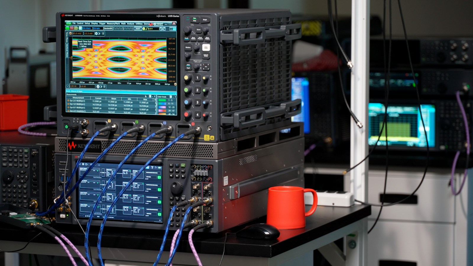
Where programming is included, image and memory verification identifies the supplied image and checks the selected programmed regions; it does not replace the operating test. If a response fails, we first check connections, applied conditions and program state, then investigate the affected circuit. After correction, we repeat affected checks and any checks needed for disturbed connections. The handoff records the applicable revisions, conditions, results and remaining deviations against the project’s acceptance scope.
Request a PCB Reverse Engineering Quote
Start with the information you have; initial photos help frame the work, while hidden connections and operating dependencies may require further assessment. Tell us what you need recovered, changed, or built so the proposed scope can distinguish engineering files from prototype or manufacturing support.
- Photos of both board sides and key connectors
- Board condition, known faults, and whether a sample can power on
- Your target: recovered design files, an approved revision, prototype, or production support
- Available schematics, BOMs, firmware or test materials, plus quantity and requested checks