
Through-Hole
PCB Assembly
Services
Build the connections your product needs.
FLJ PCB assembles connectors, terminals and other leaded components into your circuit boards. Our DIP, wave-soldering and manual resources work alongside SMT, with board fabrication, component sourcing, programming and testing available for the complete build.
Prototype boards · Small production runs · Mixed-technology assemblies

2 DIP linesThrough-hole assembly resources
2 manual soldering linesComponent-specific work
SMT + THTOne coordinated manufacturing route
Explore assembly equipmentThrough-Hole Assembly for Connectors and Leaded Components
Through-hole assembly inserts component leads into board holes and solders the intended electrical connections. It remains a practical part of many products, especially where the selected components use through-hole terminations or need a particular mechanical arrangement.
Connectors and terminals
Headers, sockets and terminal blocks connect your board with other boards, cables or field wiring. We prepare their orientation, seating and installation height around the assembly drawing and the way the connection will be used.
Power and electromechanical components
Through-hole versions of relays, transformers, capacitors and power devices can introduce different handling and heating needs. Our manufacturing preparation considers the actual package, lead arrangement and any support needed for the build.
Axial, radial and DIP packages
Leaded resistors, diodes, capacitors and dual-in-line devices add to the component mix. The actual part drawing guides fit and orientation. THT describes the assembly technology; DIP is one package type within that wider scope.
For engineering samples, see prototype PCB assembly. For ongoing small production, explore low-volume PCB assembly. FLJ brings the through-hole work into the manufacturing stage your product needs.
Through-Hole PCB Assembly Capabilities
Our through-hole service combines insertion, soldering and inspection with the wider PCB assembly. We help turn the component mix and mechanical details into a manufacturing route.
| Build area | FLJ manufacturing support | Details connected during preparation |
|---|---|---|
| Component insertion | DIP assembly resources for leaded parts | Component identity, lead condition, footprint, direction and seating |
| Soldering | Wave-soldering and manual resources | Board construction, joint access, solder materials and component heat limits |
| Mechanical arrangement | Board handling and assembly-tooling review | Finished holes, lead geometry, component height, connector alignment and support |
| Mixed-technology boards | SMT and through-hole work within the build | Previously fitted parts, solder-side clearance and inspection access |
| PCB and component supply | Turnkey, partial-turnkey and customer-supplied arrangements | Board and material readiness connected with manufacturing |
| Manufacturing completion | Selected inspection, programming and product testing | The required operating checks and delivered assembly condition |
Board dimensions, thickness, component height and tooling are considered together for the actual through-hole route. These details are matched to your files and parts during engineering preparation.
Prepare the lead, the hole and the joint together
The lead needs to fit the finished board opening and reach its intended position. The soldering process then wets the intended lead and plated connection surfaces. Lead geometry, hole position and the finished opening all contribute to the assembly fit.
Our engineers review those relationships with the actual component drawing and board information. A nominal fabrication drill size alone does not describe the finished plated opening.
1 Component lead
2 Board & plated opening
3 Soldered connection
How We Prepare and Build Your Through-Hole Assembly
FLJ connects the material kit, insertion details and soldering work. Each operation prepares the board for the next, with checks where the relevant feature is accessible.
Engineering, materials and insertion
We connect the BOM and assembly drawing with the board revision, component identity and intended configuration. Lead condition, polarity and mechanical orientation are part of that preparation.
Where lead preparation is needed, the component’s instructions guide forming and trimming. Insertion should achieve the intended seating without forcing misaligned leads into the board. Mounting height and connector alignment are checked while adjustments remain practical.
Prepare a suitable wave-soldering route
Wave soldering brings exposed joints into contact with flowing molten solder. Flux application, preheating and solder contact work together to prepare and wet the intended surfaces.
We consider the board’s copper connections, component thermal demand and any carrier when preparing the process. A large heat-sinking connection can respond differently from a smaller joint, even on the same board. Material guidance and component limits inform the thermal preparation.
Complete component-specific soldering
Manual soldering supports joints and assembly details that need local access or individual handling. FLJ plans this work around the part, joint geometry, solder materials and access available on the populated board.
Local heating still needs a suitable process. The joint must receive enough heat for wetting while the component and board remain within their applicable limits. The work is checked against the assembly’s workmanship requirements.
Inspect and prepare the delivered assembly
Relevant insertion and soldering findings feed into correction and recheck. The build can continue through programming, selected electrical or functional checks and the specified finishing and packaging.
Residue handling follows the flux system and intended delivered condition. If cleaning is included, the method is matched to the materials and components being processed, with appropriate drying.
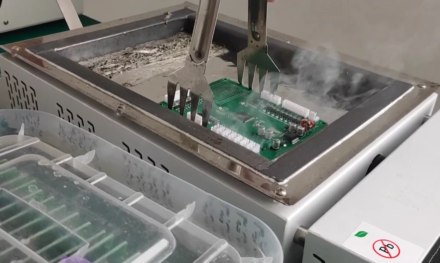
Mixed SMT and Through-Hole Assembly
One board can need several manufacturing operations. We plan how they work together.
A populated SMT board may still need connectors, relays or other inserted parts. Our team considers their installation with the components already on both board surfaces, the soldering access and the relevant inspection.
Protect fitted parts and keep the joints accessible
A carrier or shielding arrangement can support the board and protect selected areas from direct solder contact. Its openings must also give the target joints access to heat and solder. We include the carrier in thermal preparation because shielding from solder still leaves the assembly exposed to heat.
Connect the thermal and mechanical work
Existing components, large copper areas and the inserted parts affect the next operation. We review handling, component clearance and the heating needed for the actual route, alongside connector seating and the checks that follow.
Explore our SMT assembly serviceInspection and Testing for Through-Hole Assemblies
Correct insertion, sound soldering and the required product behavior are different checks. FLJ connects inspection with the manufacturing stage and adds the electrical or functional verification selected for your build.
Verify the assembled positions
Identity, polarity, seating and lead condition are checked against the build information. Connector orientation, mounting height and alignment matter when the board has to fit the next assembly or mating connection.
Inspect the relevant joint features
Visible inspection can review features such as wetting, bridges and lead protrusion. The view of an external fillet does not establish every condition inside a plated hole. Where the structure or a finding calls for further examination, we discuss the appropriate inspection scope.
Include the selected operating checks
Programming, ICT or functional testing can follow the assembly. Tests are prepared around the firmware, access and expected product responses. For a relay or connector circuit, the useful checks follow its intended function.
Use the finding to address the right operation
A seating problem calls for an insertion or mechanical review. An unsuitable joint may call for a review of solderability, local heating or access. We connect the observation with the relevant manufacturing information, then apply the correction and recheck.
Workmanship criteria are defined for the assembly and its applicable requirements. A single hole-fill percentage or a generic standard name cannot describe every joint configuration.
Inspection and product-testing supportWhy Work with FLJ PCB for Through-Hole Assembly?
Bring the board, materials and assembly work into one manufacturing discussion.
FLJ PCB is the manufacturing brand of Shenzhen Philifast Electron Co., Ltd. Our engineering, purchasing and production support helps connect component and board questions with the work needed for your assembly.
Meet FLJ PCBTwo DIP lines and two manual soldering lines, with wave-soldering support, provide resources for inserted components and product-specific work.
Seven SMT lines support surface-mount assembly within mixed builds. Our team connects the manufacturing sequence around the actual component mix.
PCB fabrication and sourcing can join the build, along with the firmware and selected testing. This helps your team discuss the delivered PCBA with one manufacturer.
Through-Hole Assembly Cost and Lead-Time Planning
A through-hole quote combines the material supply with the insertion, soldering, tooling and verification needed for the assembly. We review those elements with your quantity and intended delivery.
Components and joints both affect the work
A multi-pin connector is one component but creates multiple joints. Part types, lead preparation, insertion work and soldering access can all contribute to manufacturing effort. The route, carrier preparation and individual manual operations also affect the scope.
Selected tests, programming, finishing and packing are considered with that work. For repeat production, existing programs or tooling can be reviewed against the current board and component configuration.
Plan supply and manufacturing together
PCB and component availability, engineering questions and useful tooling can influence the schedule alongside production time. We connect material readiness with the assembly and test preparation.
Share your desired delivery when you enquire. Our team can discuss a practical schedule based on the board, component kit and work included.
Explore complete PCB assembly supportRequest a Through-Hole PCB Assembly Quote
Send your BOM, board information and quantity. Tell us what you want the completed assembly to include.
Assembly drawings, connector orientation and known installation-height or mating details help us prepare the through-hole work. Identify any boards or parts you will provide and share the programming or test needs you already know.
If your manufacturing package is still developing, send what you have. Our engineers can review the starting information and follow up on the details needed for the quote and build.
PCB assembly file guideThrough-hole assembly questions
Are THT and DIP assembly the same thing?
THT means through-hole technology. DIP means dual-in-line package, one form of leaded component. The term DIP is also used for insertion-line work, but a through-hole build can contain connectors, radial or axial parts and other packages as well.
Can you combine through-hole components with SMT?
Yes. FLJ supports mixed-technology assembly. The board population, soldering access and component requirements guide the sequence and any support or protection.
Can we provide our own PCBs or some of the components?
Yes. Customer-supplied and partial-turnkey arrangements can be included. Identify the materials you plan to provide so we can connect their preparation with the rest of the build.
Technical background
The manufacturing explanation draws on selected ST THD mounting guidance, ITW EAE’s hole-filling case and Kester’s process FAQ. Their component- and material-specific recommendations are technical background; the actual build follows its applicable part information and assembly requirements.
Related mixed-assembly example
Explore the board images, product information and design details for related projects.

Power Control System PCB Assembly
Relay-equipped PCB assembly for a power-control system, with surface-mounted components, pin headers and a multi-pin connector.