
BGA PCB Assembly
and Rework Services
Bring your BGA components into a complete PCB assembly. FLJ connects component preparation, placement and soldering with hidden-joint inspection and support for board-level rework.
From a new processor board to a component replacement on an existing assembly, our engineers help connect the device, the board and the manufacturing work.
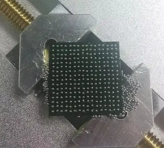
BGA Assembly Support for New and Existing Boards
High-I/O processors, memory devices and controllers often use a ball grid array. We support the assembly work that connects the device to your PCB and the rest of your product.
A BGA uses an array of solder connections underneath the package. It is a surface-mount package, assembled within the SMT manufacturing process. The position of the connections makes paste deposition, alignment, soldering and inspection closely related parts of the build.
FLJ can coordinate PCB fabrication and component sourcing with assembly, or work with the boards and parts you supply. Programming and product-specific testing can join the manufacturing plan so the delivered PCBA is prepared for its next integration step.
Assemble the BGA within your PCBA
We prepare the board, device and assembly data, connect printing and placement with the soldering process, then apply the selected checks. Other surface-mount and through-hole work can be included in the same build.
Plan component replacement or rework
Our team reviews the target device and board condition, then plans the local work and relevant recheck. This provides a practical route for a specified component change or an assembly issue that needs investigation.
See the rework processA Controlled Process for Connections Beneath the Package
The package, solder materials and PCB behave as one assembly during heating. We connect the preparation and manufacturing stages around that relationship.
Prepare the device and board
We connect the component drawing, land pattern and assembly data with the supplied board and device. Package identity, orientation, board support and access are part of preparing the build.
Moisture-sensitive components need handling that reflects their packing, exposure history and applicable supplier instructions. We consider those details before heating, including for devices already fitted to boards that need rework.
Connect solder deposition with placement
Stencil preparation and printing control the deposits on the intended pads. Solder paste inspection provides feedback before the device covers the connection area. Our team relates that feedback to the pad geometry and the selected package.
Placement preparation then connects the device orientation, position and board reference features. A suitable deposit and a correctly positioned part support the next soldering operation; placement accuracy alone does not describe the finished joint.
Prepare the thermal process for the assembly
Reflow brings the solder materials and intended surfaces together to form the connections. We prepare the process around the solder system, component requirements and thermal behavior of the populated board.
Board construction, copper distribution and package size can create different heating responses across the assembly. The useful process considers the relevant joint and component temperatures, rather than treating an oven setting as the temperature everywhere.
Connect inspection findings with the process
Printing, placement and soldering can produce different findings. We relate the observed condition to its manufacturing stage, review the relevant correction and recheck the affected work.
This keeps process improvement focused: a deposit issue, a position mismatch and an unsuitable thermal response need different investigations.
X-Ray Inspection and Verification for BGA Joints
The joint location determines which view is useful. FLJ connects hidden-joint inspection with the checks needed for your assembled board.
The BGA body conceals its connections from a conventional top-down optical view. AOI remains useful for visible assembly features, while X-ray provides another view of selected connections beneath the package.
For the connections selected for inspection, X-ray images help us review the solder-ball arrangement and investigate features such as bridging or voiding. The useful view, image interpretation and acceptance criteria follow the feature being examined. Overlapping structures or a subtle interface may call for further investigation.
Electrical and functional checks address another question: the circuit behavior defined for the product. Our team can connect the relevant inspection with programming and the selected tests, then discuss the findings or records needed for the delivered assembly.
Explore PCB and PCBA testingVisible assembly features
Component identity, position and accessible features reviewed by the applicable optical checks.
Hidden connection features
X-ray views selected around the package, joint structure and investigation.
Product response
Electrical or functional verification using the selected access, firmware and test procedure.
These checks provide complementary information. An image alone does not establish every electrical or functional result.
BGA Rework and Component Replacement
A board-level change needs a process that considers the target device, the surrounding assembly and the checks after the work.
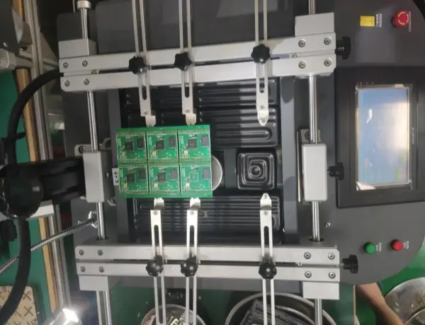
Prepare the local work and its verification
FLJ supports project-specific BGA rework within our assembly services. Our engineers start with the intended change or known finding, the device information and the board’s condition. Where failure evidence needs preserving, we discuss that before removal changes the original joint.
We plan component removal and replacement around local heating, board support and nearby components. Thermal history and moisture handling also matter when the assembly is exposed to heat again.
After removal, we inspect the exposed pads and prepare the connection site for the replacement. The work then reconnects placement and soldering with the relevant inspection and agreed electrical or functional checks.
Illustrative replacement sequence. The actual work follows the board, device and agreed objective.
Replacement, reflow and reballing are different work.
Replacing a device installs another component on the board. Reballing replaces the solder balls on a component and is a separate preparation task. The available component and board condition guide a suitable proposal; reheating alone is not a general remedy for every BGA fault.
Manufacturing Support Behind Your BGA Build
Work with a team that can discuss the board, the component kit and the finished PCBA together.
FLJ PCB is the manufacturing brand of Shenzhen Philifast Electron Co., Ltd. Seven SMT lines with Yamaha YRM20 placement resources support our surface-mount operation, alongside automatic printing, 3D SPI, reflow, AOI and X-ray resources.
Our engineering, purchasing and production teams connect those resources with your actual build. PCB fabrication and sourcing can be coordinated with assembly, while programming and product-specific tests prepare the board for the next integration stage.
For BGA work, the useful capability discussion connects the package and land pattern with handling, soldering and inspection. An equipment specification becomes useful when it is related to that manufacturing task.
Review our assembly capabilities| Resource | Manufacturing role |
|---|---|
| Automatic printing & 3D SPI | Prepare and review paste deposits before placement |
| Yamaha YRM20 placement | Position components using the released assembly data |
| Reflow soldering | Form joints using a process matched to the assembly |
| AOI & X-ray | Review visible features and selected hidden connections |
| BGA rework support | Plan local component work and the relevant recheck |
BGA Assembly Cost and Lead-Time Planning
The quotation connects materials with manufacturing preparation, assembly and verification. A package name alone does not define the work.
For a new BGA assembly
Device quantities, package and board construction, material availability and the selected inspection all contribute to the build. Process preparation, useful tooling, programming and test work can also affect the quotation.
We consider PCB and component readiness alongside manufacturing time. A long-lead processor or a board-specific preparation task can influence the schedule even when the assembly quantity is small.
For an existing board
The target device, board condition, component availability and proposed intervention help define the local work. Investigation and post-work checks may add preparation beyond the removal and replacement operation itself.
For repeat work, existing programs or tooling can be reviewed against the current revision and component. Share the intended delivery so our team can discuss a practical plan around the materials and work included.
Request BGA Assembly or Rework Support
Tell us what you want the finished board or the component work to achieve. We will review the starting information and follow up on the manufacturing details.
A new assembly
Send your board files, BOM, available assembly information and quantity. Identify the parts you will supply and any programming or test needs you already know.
An existing board
Share the device reference or part number, useful board photographs and the known problem or intended replacement. Include the board, component or previous-work records already available.
Use your existing files as a starting point. Our engineers can explain what else would help prepare the quotation and work; the assembly file guide is available when you need it.
BGA assembly questions
Is BGA assembly different from SMT?
BGA describes a package with solder connections under its body. It is assembled using surface-mount technology. The hidden joints add preparation and inspection considerations within the SMT build.
Can you work with boards or components we supply?
Yes. Customer-supplied and partial-turnkey arrangements can be discussed. Identify the materials you hold so we can connect their condition and preparation with the rest of the assembly.
Does BGA replacement always require reballing the removed device?
No. A replacement can use another suitable component. Reballing concerns the solder balls on a device and is separate from replacing that device on the PCB. We review the proposed component and board-level work before defining the route.
Technical background includes Meixin HiP explanation, TI’s flip-chip BGA guide and Indium’s HiP discussion. Their device- and material-specific guidance informs the explanation; the actual build follows its applicable component and process requirements.