Introduction
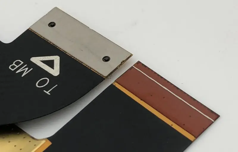
FPC stiffening does more than hold parts. It can also help with heat dissipation. But if you need to rework or repair the board, removing the stiffener may damage the traces. Keep that in mind.
1. Special Treatments for FPC Stiffening
Special designs can make a stiffener do more than support parts. For example, while the main goal is to support parts, the stiffener can be made as a supporting component so the flex board behaves more like a rigid board after assembly.
Stiffener contouring (shape cutting) is usually done with CNC routing equipment. During cutting, some connection points or bridges are left so the stiffener can be removed or broken off later. This lets the stiffener be broken or removed easily after assembly.

CNC routing is common in flex manufacturing. Laser cutting and waterjet cutting are also options. They can be used to prepare or pre-cut stiffener material. For boards with height differences, non-press cutting methods like laser or waterjet can simplify the process. They also cut cost because no stamping tool is needed.
2. Mechanical Processing of Stiffeners (Stamping / Die-Cutting)
2.1 Stamping / Die-Cutting
If the stiffener production uses mesh stamping or die-cutting, special stamping dies are needed. After stamping removes the hard material around parts, the remaining sheet can be pushed back to its original position. This method is common for low-cost rigid boards and for high-volume assembly using simple fixtures.
2.2 Scoring or Partial Cutting
If the flex outline allows, scoring or partial-cut tools can be used. Scoring usually cuts partway through the flex or the stiffener. Special tools control cut depth. After parts are placed and assembly is finished, the board can be broken along the score line.
Compared with routed contouring, most other cutting techniques must cut all the way through the material. Because of the nature of mechanical cutters, cut shapes are usually straight lines.
3. Adhesives for Stiffener Bonding
Adhesives used to bond stiffeners to flex substrates are chosen by their required function. Besides standard adhesives for flex, there are other adhesive types. Common stiffener adhesive types and features:
3.1 Pressure-Sensitive Adhesive (PSA)
PSA is widely used for stiffeners. It is flexible and easy to use. It gives good bond strength and can improve durability in some cases. Most PSAs are not designed for long-term high-temperature use, and they usually only tolerate short high-temperature exposure. With lead-free soldering (higher reflow temperatures), check if the PSA works in the required process. A special advantage of PSA is that it lets the flex stick to almost any surface, so many built-in stiffening designs are possible.
3.2 Thermoset Adhesive Films
Thermoset adhesive films, sometimes called acrylic-coated films or bonding sheets, can bond stiffeners and flex. They need extra processing steps and time. Still, thermoset adhesives can give very high bond strength and high temperature resistance.
3.3 Liquid Adhesives
Single-part or two-part epoxy adhesives are used to bond stiffeners. They are hard to apply evenly, so they are less common than film adhesives. When used, liquid adhesives form a gradual epoxy bead at the bond edge. This bead helps relieve strain at the transition edge.
3.4 Thermoplastic Adhesive Films
Thermoplastic adhesive films are another common choice. They have low stress and are fully polymeric without needing a chemical cure. They bond to many surfaces and are reported to be easy to rework. These features broaden their use.
3.5 UV Cure Adhesives
UV-curing adhesives are another option. Some formulas are screen-printable. Some UV-activated polymers can show PSA-like tack after activation. Because they cure fast, UV adhesives are useful for designs that need a quick soft-hard transition and strain relief.
4. Holes in Stiffeners (Clearance Holes, Assembly Holes, Mounting Holes)
Holes for part clearance and holes for final assembly are different and sometimes have opposite effects. Design rules must match the intended use. Design data must explain how to choose hole diameters.
If you ignore this in design or manufacturing, you may see gaps or copper breaks at junctions between part holes and copper. You may need later fixes.
4.1 Component Clearance Holes in the Stiffener
Holes that clear plated through-holes should be 250 µm – 375 µm larger than the plated through-hole. This compensates for possible misalignment during lamination and helps ensure the plated holes are not blocked by the stiffener.
4.2 Assembly / Mounting Holes
Holes in the stiffener made for assembly should be slightly smaller than the holes in the flex. That helps keep assembly stress from moving to the flex. This is not always required. In some designs, the flex may be attached directly to a carrier without a stiffener.
4.3 Unsupported Mounting Holes
For mounting holes that do not have stiffener support, keep copper around the hole (annular ring) to add strength. If the design allows, the same method can be used for normal mounting holes. This shape also makes grounding easier.
5. Common FPC Stiffener Materials and Their Features
FPC commonly uses three stiffener materials: PI, FR4, and stainless steel. Details:
5.1 PI (Polyimide)
PI is a specialty engineering material. It is widely used in aerospace, microelectronics, nanotech, LCDs, separation membranes, and lasers. It is flame-retardant and resists high and low temperatures. Long-term use temperature ranges vary by grade, but PI can handle a wide range. In FPC, PI is used as protective film and as stiffener sheets. PI protective film insulates circuits. PI stiffeners are used on the back of gold fingers and other areas needing insulation and reinforcement. PI stiffener thickness is chosen by the design and environment. Tolerance can be controlled to ±0.03 mm. PI handles process temperatures well (commonly 130 °C–280 °C, depending on grade). Common PI stiffener thicknesses: 0.075 mm, 0.1 mm, 0.125 mm, 0.15 mm, 0.175 mm, 0.2 mm, 0.225 mm, 0.25 mm.
5.2 FR4
FR4 is a flame-retardant material. Compared to paper-based boards, it has better mechanical strength, dimensional stability, impact resistance, and moisture resistance. Its electrical performance is good and it works at higher temperatures. In processing, it often has advantages over other resin-glass-fiber boards. In FPC production, FR4 is mainly used as a stiffener behind soldering areas. It increases hardness at the solder area and protects surface-mount parts from failure caused by repeated flexing. Because FR4 wears more than PI, it is usually not used for gold-finger stiffening. For FR4 stiffeners: if thickness < 0.1 mm, tolerance can be ±0.05 mm; if thickness > 1.0 mm, tolerance is ±0.1 mm. Common FR4 stiffener thicknesses: 0.1 mm, 0.2 mm, 0.3 mm, 0.4 mm, 0.5 mm, 0.6 mm, 0.7 mm, 1.6 mm.
Quick comparison: PI has tighter tolerances and good heat resistance but is not very hard. FR4 is thicker and stiffer, has larger tolerances, and is more stable for manual assembly but harder to rework.
5.3 Steel Stiffeners (Stainless Steel)
Usually 303 stainless steel. 303 is an austenitic stainless steel with sulfur and selenium to improve machinability and surface finish. FPC stiffeners often have complex shapes, and 303 stainless is easy to etch. For FPC products needing high stability, 303 steel stiffeners are common. Steel stiffeners cannot be drilled with CNC or cut by FPC laser. They are usually produced by chemical etching, so the cost is higher. They need manual assembly, the process is more complex, and cost is higher. Common steel stiffener thicknesses: 0.1 mm, 0.2 mm.
6. Design Points and Practical Advice
When you design stiffeners and holes, be clear about each hole’s purpose (clearance, assembly, mounting). State hole diameter, tolerance, and position tolerance in the design notes.
For stiffeners near plated holes, leave enough clearance or enlarge the hole by 250–375 µm to avoid blocking plated holes during lamination.
If the stiffener will bear assembly or mechanical stress, consider harder materials like FR4 or steel. But if future rework is likely, prefer PI or thermoplastic film solutions that are easier to rework.
When you choose adhesives, consider reflow temperatures (especially for lead-free soldering), rework needs, long-term environment (temperature, humidity), and the surfaces to be bonded.
For complex shapes or high-precision stiffeners, prefer chemical etching or laser cutting to lower tooling cost. For large volumes and regular shapes, consider stamping or die-cutting to reduce unit cost.
If you need to remove a stiffener after assembly, leave bridges or score lines between the stiffener and the flex so it can be broken or removed later.
7. Summary (Pros and Cons)
PI stiffeners: tight tolerance, good high-temp resistance, easy to integrate with flex, good reworkability; not as hard as FR4.
FR4 stiffeners: thicker, harder, more stable for solder areas; larger tolerance, harder to rework.
303 steel stiffeners: very rigid and stable, but higher cost, made by etching, need manual assembly, and rework is difficult.