


Getting an accurate printed circuit board assembly quote hinges on one critical factor: the completeness of your documentation package. Manufacturing partners can’t price what they can’t see, and incomplete submissions trigger rounds of back-and-forth emails that delay production timelines by days or weeks. Understanding pcba quote requirements upfront eliminates these bottlenecks and accelerates your project from concept to production.
The typical PCBA quote package contains three core elements: design files that define your board’s physical structure, a bill of materials listing every component, and fabrication specifications detailing manufacturing constraints. Assembly houses need complete visibility into both the PCB itself and the components that populate it. Missing even a single file—whether it’s your Gerber data, your BOM, or your assembly drawings—forces manufacturers to make assumptions or request clarifications. The cost of incomplete documentation extends beyond timeline delays. Manufacturers may pad quotes to account for uncertainty, quote based on incorrect assumptions, or simply decline to bid on projects lacking essential information. A well-prepared file package, however, enables manufacturers to identify potential design issues early, suggest cost-saving alternatives, and provide accurate pricing that reflects your actual production requirements. The documentation you submit directly determines both the speed and accuracy of your quote response.
Essential Files for a PCBA Quote
Your pcb assembly quote files package functions as the technical blueprint manufacturers use to calculate costs and assess feasibility. At minimum, expect to provide three core file categories: fabrication data, assembly instructions, and component specifications. Fabrication and assembly documentation forms the foundation of accurate quoting. Gerber files define your board’s physical structure—copper layers, solder mask, silkscreen, and drill patterns. Bill of Materials (BOM) spreadsheets list every component with manufacturer part numbers and reference designators. Pick-and-place (centroid) files specify exact component locations using XY coordinates.
However, basic files alone rarely suffice. Manufacturers need context to quote accurately. Assembly drawings clarify component orientation and special handling requirements. PCB stack-up documents detail layer construction and material specifications. Complete fabrication notes should specify finish types, impedance control requirements, and any deviations from IPC standards.
Missing documentation triggers assumptions—and assumptions inflate costs. A comprehensive file package eliminates guesswork, reduces back-and-forth communication, and accelerates quote turnaround from days to hours. Smart documentation preparation distinguishes experienced designers from novices navigating their first manufacturing partnership.
Gerber Files: The Backbone of PCB Manufacturing
Gerber files translate your circuit board design into a language fabrication equipment understands. These industry-standard files contain layer-by-layer instructions for copper traces, soldermask, silkscreen, and drill locations. Without properly formatted Gerbers, manufacturers cannot accurately estimate material requirements or production complexity—two primary cost drivers. Modern Gerber X2 format improves on legacy RS-274X by embedding metadata about layer functions directly within each file, reducing misinterpretation risks. When preparing files required for pcba quotation, your Gerber package typically includes copper layers (top, bottom, internal), soldermask layers, silkscreen layers, and paste mask layers for SMT components. Each layer must maintain registration accuracy within ±0.003 inches to prevent alignment failures during manufacturing. Common pitfalls include missing layers or incorrect file extensions. A complete package should contain individual files for each functional layer rather than merged composites. Manufacturers use these files to program drilling machines, apply soldermask, and verify trace clearances—processes that directly impact your quoted price and lead time.
Bill of Materials (BOM): The Inventory Blueprint
While gerber files for pcb quote submissions define your board’s physical structure, the Bill of Materials (BOM) specifies every component that populates it. This spreadsheet-style document creates the foundation for accurate cost calculations, with manufacturers requiring specific data columns to process your assembly quote.
A comprehensive BOM typically includes manufacturer part numbers, reference designators, component quantities, and descriptions. Reference designators (like
- R1
- C5
- U3) map each line item to specific board locations
- enabling assemblers to verify that your pick-and-place data aligns with your component inventory. Part numbers must match manufacturer specifications exactly—generic descriptions like “10K resistor” create ambiguity that delays quotes and risks assembly errors.
Beyond basic identification, include package types (0603, SOT-23, QFN-48), tolerance specifications, and approved substitutes. Assembly houses use this information to identify potential sourcing challenges, such as obsolete components or long lead-time parts that impact your project timeline and budget. One practical approach involves adding columns for alternate part numbers, particularly for passive components where multiple manufacturers offer equivalent specifications at varying price points.
Pick-and-Place Data: Optimizing Assembly
Pick-and-place files tell automated assembly machines exactly where to position each component on your board. These files, typically exported as centroid or XY coordinate files, contain precise placement coordinates, rotation angles, and component designators that guide the assembly process. The format matters. While most machines accept CSV or TXT formats, column ordering varies between manufacturers. A standard centroid file typically includes designator, X-position, Y-position, rotation, and layer information. Double-check your file includes both top and bottom layer data if you have a double-sided assembly. Accurate pick-and-place data directly impacts assembly speed and cost. Errors in rotation angles or coordinates force manual corrections, adding labor hours to your quote. Cross-reference your centroid file against your BOM requirements for PCB assembly—mismatches between component designators signal potential issues before they reach the factory floor.
Export these files from your PCB design software’s assembly output menu. Most platforms generate them automatically, but verify the origin point matches your manufacturer’s requirements. Some use the board’s lower-left corner; others reference the center point. This seemingly minor detail prevents costly placement errors during production.
4 Documents Required to Quote a Pcb Assembly
Beyond the technical files, manufacturers need supporting documentation to provide accurate quotes and ensure successful assembly. Assembly drawings for pcb quote submissions serve as visual guides that communicate mechanical requirements, component orientations, and special handling instructions that aren’t captured in CAD files alone.
The assembly drawing shows the finished board from a human perspective—where each component sits, part numbers, polarity markers, and reference designators. These drawings help assembly technicians verify correct component placement and catch potential issues before production begins.
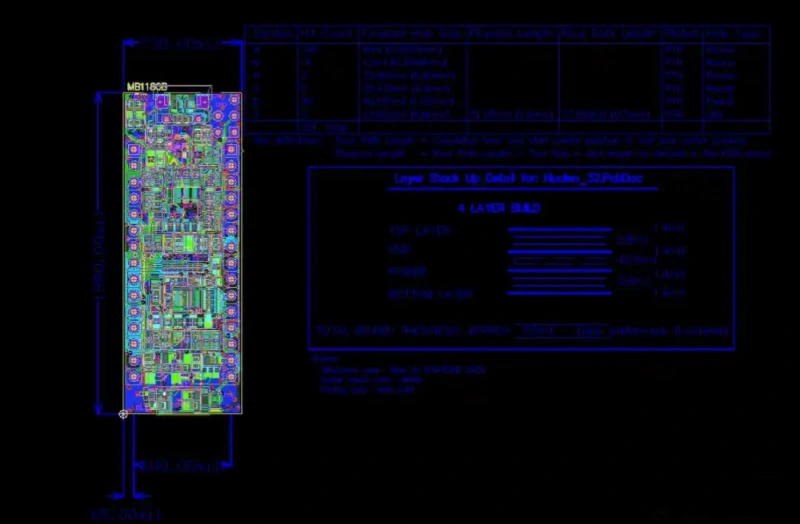
A comprehensive fabrication drawing specifies the physical board characteristics: finished dimensions, layer stackup, material specifications, solder mask colors, and surface finish requirements. This document bridges the gap between your design intent and the manufacturer’s capabilities.
Your component specifications list provides detailed information about each part: manufacturer names, exact part numbers, acceptable substitutes, and special procurement notes. This prevents assembly delays caused by component sourcing issues or ambiguous part descriptions. Finally, include assembly notes that detail special requirements: conformal coating specifications, specific torque values for mechanical fasteners, depanelization instructions, and or testing requirements. These instructions ensure your manufacturer understands project-specific needs that standard files can’t communicate.
Additional Documentation Needed
Beyond the core technical files, manufacturers require supplementary documents that clarify your PCB fabrication drawing requirements and assembly expectations. An assembly drawing or fabrication drawing provides visual context that technical files alone cannot convey—showing component orientation, board dimensions, tooling holes, and mechanical constraints. This single-page reference document helps assembly technicians quickly verify placement accuracy without parsing through raw data files. Include a detailed Bill of Materials (BOM) that extends beyond simple part numbers. Specify manufacturer part numbers, approved alternates, reference designators, and any special handling notes. PCB manufacturers need complete component information to source parts accurately and flag potential obsolescence issues before production begins.
Quality assurance documentation defines your acceptance criteria. Specify IPC standards (typically IPC-A-610 Class 2 or 3), testing requirements, and inspection protocols. If you require conformal coating, panelization, or specific packaging, document these requirements explicitly—assumptions often lead to costly misunderstandings during fulfillment.
This comprehensive documentation package sets clear expectations and minimizes revision cycles during quoting. However, even with complete files, preparation mistakes can derail the process.
Common Mistakes in File Preparation
Even experienced designers fall into predictable traps when preparing documentation. Incomplete Gerber file sets top the list—missing layers like silkscreen or soldermask can halt production immediately. Sierra Circuits notes that manufacturers often receive partial file packages that require multiple clarification rounds.
Mismatched BOM and centroid data creates assembly chaos. When component designators in your BOM don’t align with pick-and-place coordinates, assemblers waste time reconciling discrepancies or may place parts incorrectly. Version control failures compound this—submitting outdated files from different design revisions guarantees errors.
Format issues plague many submissions. Sending native CAD files instead of industry-standard Gerber or ODB++ formats forces manufacturers to interpret your design, introducing potential mistakes. Using non-standard file extensions or compressing multiple projects into one archive without clear organization creates unnecessary confusion.
A comprehensive pcb assembly documentation checklist prevents these pitfalls. Include all Gerber layers, properly formatted drill files, current BOM with manufacturer part numbers, accurate centroid data, and clear assembly drawings. Philifast emphasizes verifying that component rotation angles in your pick-and-place file match your assembly house’s conventions—a 90-degree discrepancy can misalign entire component rows. Rushing file preparation to meet deadlines almost guarantees costly revisions later.
Trade-offs and Considerations
When preparing files for PCBA quotes, designers face practical trade-offs that affect both turnaround time and project outcomes. Complete documentation takes time but prevents costly delays later—a quick submission with minimal files might get a fast quote, but manufacturers will inevitably request clarifications that stretch the timeline.
File format choices present another balance. Industry-standard Gerber files ensure universal compatibility but require careful export settings. Conversely, proprietary formats like ODB++ carry more data automatically but limit manufacturer options. According to Sierra Circuits, selecting formats based on your manufacturer’s capabilities rather than theoretical “best practices” often yields better results.
Documentation depth creates a similar tension. Overly detailed specifications can introduce unnecessary constraints that increase cost, while vague requirements leave room for interpretation that may not align with your expectations. The sweet spot lies in specifying critical parameters explicitly—material type, finish requirements, inspection criteria—while allowing manufacturers flexibility on implementation details. Summit Interconnect notes that boards with clear but concise specifications typically receive more competitive quotes because manufacturers can optimize their processes without excessive back-and-forth clarification.
Example Scenarios: File Submissions in Practice
Real-world file submissions reveal patterns that separate smooth quotes from project delays. A simple two-layer prototype submission typically includes Gerber files, a single BOM listing standard components, and basic assembly drawings—often processed within hours when complete. One common pattern shows designers submitting just the Gerbers initially, then adding the BOM after receiving fabrication pricing, which fragments the quoting process unnecessarily. Complex multi-layer boards follow a different trajectory. A medical device project might include fifteen Gerber layers, detailed impedance specifications in fabrication notes, and a BOM with controlled lifecycle components requiring traceability documentation. These comprehensive packages often receive faster turnaround than simpler projects with incomplete files because manufacturers can immediately verify feasibility and pricing. What typically happens with RF designs illustrates documentation importance. Without clearly documented impedance requirements and stack-up specifications, manufacturers default to standard processes—potentially compromising performance. Including a cross-sectional stack-up diagram and specific dielectric requirements eliminates this ambiguity. These practical differences demonstrate how file completeness directly correlates with quote accuracy and project success, setting up clear principles worth remembering.
Key Pcba Quote Requirements Takeaways
Complete file packages accelerate quotes and reduce revision cycles. The core requirement remains consistent across manufacturers: Gerber files for fabrication, a bill of materials with full part specifications, a centroid file with precise component coordinates, and fabrication drawings that eliminate ambiguity. Missing any of these elements triggers clarification requests that add days to the quoting process.
File quality matters more than file quantity. A lean submission with accurate designators, verified coordinates, and manufacturer part numbers outperforms bloated packages with incomplete data. What separates smooth quotes from problematic ones isn’t additional documentation—it’s the precision of essential files.
Assembly complexity determines documentation depth. Simple two-layer prototypes need minimal supporting files, while mixed-technology boards with fine-pitch components require detailed assembly drawings, panel specifications, and explicit testing requirements. The pattern holds across projects: complexity demands clarity.
Preparation time invested upfront saves revision cycles later. Verifying part availability before submission, confirming centroid alignment, and including clear special instructions prevents the back-and-forth that delays production schedules and increases costs.
4 Documents Required to Quote a Pcb Assembly
Complete file packages accelerate quotes and reduce revision cycles. The core requirement remains consistent across manufacturers: Gerber files for fabrication, a bill of materials for component sourcing, assembly drawings for placement clarity, and Centroid data for automated equipment. These four document types form the foundation of any PCBA quote request, regardless of project complexity or production volume.
The efficiency of your quote request directly correlates with file completeness. A manufacturer receiving all four document types in standard formats can typically return a quote within 24-48 hours. Missing even one element—particularly the BOM or Centroid file—extends this timeline as engineers request clarification or reverse-engineer missing data from other files.
Moving from quote to production becomes seamless when files meet both fabrication and assembly requirements simultaneously. Projects that include comprehensive test procedures, clear special instructions, standardized file formats consistently experience fewer revision cycles, and shorter lead times. The investment in proper file preparation at the quoting stage pays dividends throughout the entire manufacturing process, from initial cost estimation through final quality verification.

