

















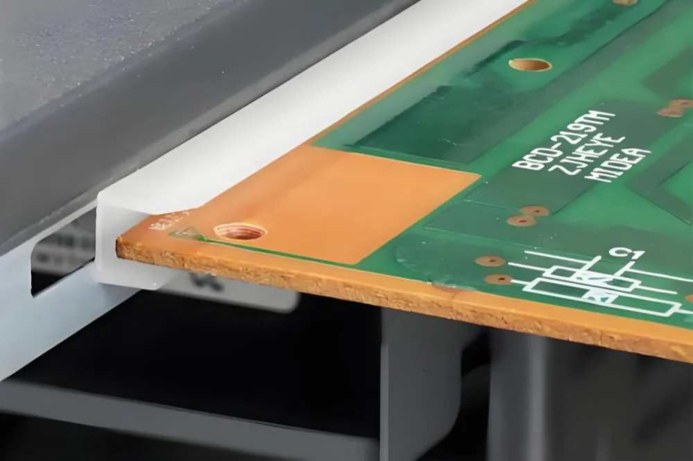
What Tg Means in PCB Engineering
In a multilayer board going through a lead-free reflow cycle, the real problem isn’t melting—it’s what happens to the resin at the glass transition temperature (Tg). Tg is the point where the polymer matrix shifts from a rigid, glass-like state to a softer, rubbery one. This is measured using Differential Scanning Calorimetry (DSC) or Thermomechanical Analysis (TMA), and the reported Tg value is that inflection point, typically in degrees Celsius.
Thermal Behavior at the Tg Point
The practical concern isn’t a sudden failure but a rapid, non-linear increase in the coefficient of thermal expansion (CTE). Below Tg, the Z-axis expansion is relatively constrained, maybe 50-60 ppm/°C. Once the material crosses that thermal threshold, the expansion rate can spike to 250-300 ppm/°C almost instantly. This is where the damage accumulates. The resin expands aggressively, but the copper barrels in plated through-holes and buried vias don’t move at the same rate. The resulting shear stress concentrates at the weakest interface, usually the plating knee or the inner-layer interconnection.
| Substrate Type | Tg (°C) | CTE (below Tg, ppm/°C) | CTE (above Tg, ppm/°C) | Z-axis CTE Ratio |
|---|---|---|---|---|
| Standard FR-4 | ~130–140 | 50–70 | 250–300 | ~4–5x |
| Mid-Tg FR-4 | ~150 | 45–65 | 220–270 | ~4x |
| High-Tg FR-4 | ~170–180 | 40–60 | 200–250 | ~4x |
| Polyimide | ~250+ | 35–50 | 120–150 | ~3x |
| PTFE (Teflon) | N/A | 20–30 | No distinct Tg inflection | ~1x |
Why the Tg Value Matters for Reliability
A standard FR4 with a Tg of 130°C sounds safe for a 100°C operating environment, but that margin disappears fast during assembly. Lead-free soldering peaks above 245°C, and the board goes through that heat multiple times for double-sided SMT. A High-Tg PCB with a Tg value above 170°C doesn’t eliminate expansion—it simply delays the catastrophic rise in CTE until a higher temperature. This keeps the material in its stable glassy state through more of the thermal cycle, which is why it’s non-negotiable for designs with heavy copper or via-in-pad structures. You can see the difference in cross-sections after thermal shock testing: the standard material shows corner cracks and pad cratering, while the high-Tg variant maintains its structural integrity through the same stress profile.
Why Standard FR4 Fails in High-Heat Environments
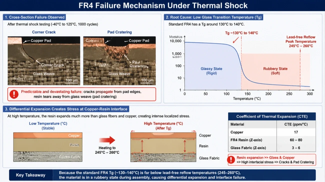
In cross-section analysis after thermal shock testing, the failure pattern in standard FR4 is predictable and devastating. You see corner cracks propagating from the pad edges, and pad cratering where the resin has literally torn away from the glass weave. The root cause comes down to one property: the glass transition temperature, or Tg.
A standard FR4 substrate has a Tg around 130°C to 140°C. During lead-free assembly, peak reflow temperatures hit 245°C to 260°C. At this point, the material has already transitioned from a rigid, glassy state into a soft, rubbery phase. The resin expands rapidly in the Z-axis, but the glass fabric and copper don’t move at the same rate. This differential expansion creates intense localized stress at every copper-resin interface.
Delamination Mechanisms
Delamination starts at the weakest points in the laminate. These are typically the resin-rich areas between prepreg layers or around the pad shoulders where plating meets the base material. During reflow, moisture trapped in the board rapidly turns to steam. The vapor pressure, combined with the softened resin state, pushes layers apart. We’ve pulled boards off the line where the inner layers separated so cleanly you could slide a razor blade between them. Post-reflow, the damage is often hidden until thermal cycling in the field causes the micro-voids to grow into open circuits.
Via Barrel Cracking
The other common failure is via barrel cracking. The Z-axis CTE of standard FR4 above Tg can spike to over 200 ppm/°C, while copper stays near 17 ppm/°C. The board expands vertically much more than the plated copper barrel can stretch. After repeated cycles, the copper work-hardens, becomes brittle, and cracks at the mid-point of the via or at the knee where the pad connects to the barrel. In high-layer-count boards, we’ve measured Z-axis expansion exceeding 5% of the total board thickness during a single reflow pass. That’s enough to fracture a 1-mil thick via wall in one shot. High-Tg materials push this transition point to 170°C or higher, keeping the resin in its stable, low-expansion state throughout the entire thermal profile.
Material Systems for High-Tg Boards
When a board goes through a lead-free reflow cycle, the material choice is the single biggest factor determining whether the plated vias survive intact. Three high-Tg materials dominate the conversation in rigid multilayer production: Isola 370HR, Shengyi S1000-2, and ITEQ IT-180A. They are not interchangeable. Each behaves differently under thermal stress, and the differences show up clearly in cross-section analysis after thermal cycling.
| Property | Isola 370HR | Shengyi S1000-2 | ITEQ IT-180A |
|---|---|---|---|
| Tg (DSC) | 180°C | 180°C | 180°C |
| Td (5% weight loss) | 350°C | 350°C | 350°C |
| Z-axis CTE (below Tg) | 45 ppm/°C | 45 ppm/°C | 45 ppm/°C |
| Z-axis CTE (above Tg) | 260 ppm/°C | 260 ppm/°C | 260 ppm/°C |
| Z-axis expansion (50–260°C) | 3.0% | 3.0% | 3.0% |
| T260 (delamination) | >60 min | >60 min | >60 min |
| T288 (delamination) | >15 min | >15 min | >15 min |
| Dk @ 1 GHz | 3.92 | 3.90 | 3.90 |
| Df @ 1 GHz | 0.020 | 0.020 | 0.020 |
| Copper peel strength | 1.2 N/mm | 1.2 N/mm | 1.2 N/mm |
| Flammability | V-0 | V-0 | V-0 |
| IPC spec compliance | IPC-4101 /99 /102 /126 | IPC-4101 /99 /126 | IPC-4101 /99 /126 |
| Lead-free compatible | Yes | Yes | Yes |
Thermal Stability and Tg Range
All three materials are classified as mid-range high-Tg systems. Isola 370HR has a Tg of approximately 180°C by DMA. Shengyi S1000-2 also lands around 180°C. ITEQ IT-180A sits slightly lower, typically 175–180°C. These numbers are close on a datasheet, but the real distinction is not the glass transition temperature itself — it is how the material behaves after Tg.
The decomposition temperature, or Td, tells a more useful story for lead-free assembly. 370HR has a Td around 350°C. S1000-2 is comparable, around 345–350°C. IT-180A measures slightly lower, usually 340–345°C. A 5–10°C difference in Td does not sound significant, but in a 260°C peak reflow profile with multiple cycles, the cumulative thermal budget pushes lower-Td materials closer to degradation onset. We see this in production as resin discoloration near heavy copper planes after two reflow passes.
Z-Axis Expansion and Via Reliability
The parameter that matters most for via reliability is the Z-axis coefficient of thermal expansion (CTE) above Tg. Isola 370HR is known for a tightly controlled Z-CTE, typically around 3.5% total expansion from 50°C to 260°C. This is the benchmark many fabricators use when qualifying a new high-Tg laminate.
Shengyi S1000-2 performs similarly in most builds — around 3.5–3.8% total Z-expansion — but the consistency depends heavily on the press cycle. In shops that run aggressive cycle times, S1000-2 can show slightly higher expansion variation from lot to lot. ITEQ IT-180A tends toward 3.8–4.2%, which is still acceptable for IPC Class 2 work but becomes a concern in high-layer-count boards or thick backplanes where absolute expansion distance is larger.
A 0.5% difference in Z-expansion may seem trivial. In a 2.4 mm thick board, that translates to roughly 12 µm more absolute expansion. When a 0.25 mm via has a 25 µm plated wall, that extra movement directly increases the strain on the copper. After 500 thermal cycles from -40°C to 125°C, the difference shows up as higher via failure rates in IT-180A builds compared to 370HR.
Processing Behavior in the Shop
From a fabrication standpoint, the three materials behave differently during drilling and desmear. Isola 370HR produces clean hole walls with standard desmear chemistry. The resin smears predictably, and permanganate etching removes it without excessive glass fiber attack.
Shengyi S1000-2 is slightly harder on drills. We typically see 10–15% higher drill wear rates compared to 370HR when running the same stack height and hit count. The desmear step also requires tighter control — the resin is marginally more resistant to permanganate, so under-desmear defects appear earlier if the line speed is not adjusted.
ITEQ IT-180A processes easily. Drill wear is comparable to 370HR, and desmear is straightforward. The trade-off comes later: the cured resin is slightly more brittle, which increases the risk
IPC-4101 and the Tg Classification System
Not all high-Tg laminates are the same. The industry sorts them using IPC-4101 slash sheets, and the differences matter more in production than they do on a datasheet.
The Slash Sheet Structure
IPC-4101 doesn’t give you one spec for “high-Tg.” It breaks materials into slash sheets — each one a separate performance bracket. For rigid FR-4 laminates, the common ones are /99, /101, /102, /121, /124, /126, and /129. The number isn’t random. It locks down resin chemistry, filler content, Tg minimum, and thermal reliability test requirements.
A /126 laminate, for example, requires a Tg of at least 175°C by DSC and must pass solder float at 288°C for 10 seconds after thermal stress. A /99 sheet sits lower — 150°C Tg minimum, different decomposition temperature thresholds. When a fab shop sees “IPC-4101/126” on a fabrication drawing, they know exactly what laminate family qualifies. No guessing.
What Tg Ranges Actually Mean for Qualification
Tg classification splits into three practical buckets:
| Tg Range | Typical Slash Sheets | Real-World Meaning |
|---|---|---|
| Standard (130–150°C) | /99, /101 | Fine for consumer electronics, single-sided reflow. Margin gets thin above 260°C peak. |
| Mid (150–170°C) | /121, /124 | Handles multiple lead-free reflow cycles. Common in industrial and automotive tier-2. |
| High (175°C+) | /126, /129 | Required for high-layer-count boards, long-duration thermal cycling, and RF power applications. |
But here’s the catch: Tg alone doesn’t qualify a laminate. A material can hit 180°C Tg and still fail solder float if the resin system has poor thermal decomposition behavior. That’s why IPC-4101 slash sheets also specify Td (decomposition temperature) and T260/T288 time-to-delamination. I’ve seen laminates with impressive Tg numbers delaminate at 260°C in under 5 minutes because the Td was too close to the reflow peak.
So when you specify a high-Tg PCB, don’t just write “Tg > 170°C” on the fab notes. Reference the slash sheet. It forces the laminate to meet a full thermal profile, not just one number. Shops that stock ITEQ IT-180A or Isola 370HR already align to /126 or /129 requirements. The qualification path is shorter because the material is pre-qualified against the slash sheet’s full test battery.
Also worth noting: Tg classification doesn’t address CAF resistance or Z-axis CTE directly. Those come from reinforcement style and resin formulation — topics covered under separate IPC test methods. A high-Tg PCB with poor resin toughness can still crack vias during thermal cycling, even if the Tg number looks safe on paper.
Z-Axis Expansion and Plated Through-Hole Reliability
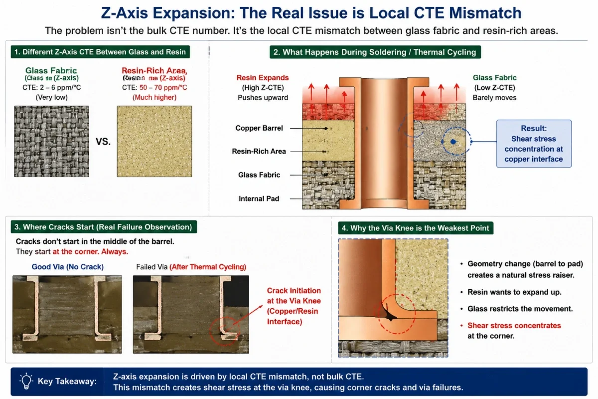
The real problem with Z-axis expansion isn’t the bulk CTE number you see on a datasheet. It’s the local CTE mismatch between the glass fabric and the resin-rich areas around a plated through-hole.
In a standard FR4 board, the resin expands at 50–70 ppm/°C in the Z direction. The glass fabric barely moves. During soldering or thermal cycling, the resin pushes upward while the glass stays put. This creates a shear stress concentration right at the copper barrel — specifically at the knee of the via, where the plated copper meets the internal pad.
I’ve seen cross-sections from failed boards where the crack doesn’t start in the middle of the barrel. It starts at the corner. Always.
Why Tg Alone Doesn’t Fix It
A common mistake is treating Tg as a magic threshold. Engineers specify “Tg > 170°C” and assume via reliability is solved. That’s not how it works.
Tg tells you where the resin softens. Below Tg, the Z-axis expansion is relatively controlled — maybe 2.5% to 3.0% total expansion from room temperature to 150°C. Above Tg, the expansion rate jumps 3x to 5x. So if your process spends significant time above Tg — which lead-free reflow absolutely does — the via barrels experience most of their stress in that window.
But here’s the manufacturing reality: a high-Tg board with a brittle resin system can still fail. I’ve run thermal shock tests on 180°C Tg materials that cracked vias after 200 cycles, while a tougher 150°C Tg system survived 500+ cycles. The difference was resin toughness, not the Tg number.
What Actually Happens During Reflow
During lead-free assembly, the board hits 250°C to 260°C at peak. At that temperature, the resin expansion is significant — especially in thick boards above 2.4mm. A via in a 3.2mm board can see Z-axis expansion of 80–100 microns. The copper barrel must stretch to accommodate this.
If the copper elongation is too low — common with some high-ductility but low-tensile copper plating — the barrel thins at the knee and eventually cracks. If the resin is too brittle, it micro-fractures around the hole wall, creating initiation points for copper cracking on the next cycle.
The practical fix isn’t just higher Tg. It’s selecting a resin system with low Z-axis CTE below Tg (ideally under 45 ppm/°C) and high elongation above Tg. Materials like mid-loss polyimides and certain halogen-free formulations perform well here — not because of Tg alone, but because the full expansion curve is flatter across the thermal range.
One more thing: board thickness matters more than most designers realize. A PCB thickness increase from 1.6mm to 3.2mm roughly doubles the total Z-axis displacement. If you’re designing a thick backplane with high-Tg materials, you need to derate your expected via life accordingly — or switch to a lower-CTE laminate like polyimide for critical layers.
I’ve also seen heavy copper PCBs worsen the problem. Thick internal planes act as constraint layers that restrict in-plane expansion, forcing even more strain into the Z-axis. The vias take the hit.
For boards going through extended thermal management cycling — think under-hood automotive or downhole equipment — via reliability isn’t a material spec problem. It’s a system-level stress problem. And the solution starts with understanding that Z-axis expansion is never uniform across the hole wall.
Lead-Free Soldering and the Shift to High-Tg
When the European Union’s RoHS directive took effect in 2006, it didn’t just eliminate lead from solder. It changed the thermal reality of every assembly line. Traditional tin-lead solder reflowed at around 220°C. The lead-free SAC305 alternative needed 240–250°C, sometimes peaking at 260°C. That 20–30°C difference doesn’t sound dramatic on paper. On the factory floor, it was enough to expose a material limitation that many designers had ignored for years.
Standard FR4 with a Tg of 130–140°C starts softening well before peak reflow. When the board enters the liquidus zone, the resin expands rapidly in the Z-axis. Copper barrels inside plated through-holes don’t expand at the same rate. The stress concentrates at the knee of the hole wall, where the barrel meets the innerlayer pad. After a few lead-free cycles, microcracks start. Sometimes they’re visible. Sometimes they only show up later, during thermal cycling in the field.
Why Higher Tg Became a Production Requirement
The shift wasn’t about making boards survive higher operating temperatures. It was about surviving assembly. A board with a Tg of 170°C or higher stays rigid through the entire lead-free profile. The resin doesn’t enter its rubbery phase during reflow, so Z-axis expansion stays more controlled. This reduces instantaneous stress on via barrels and pad connections.
Most manufacturers now specify mid-Tg (150°C) as a minimum for lead-free processes. High-Tg (170–180°C) became standard for multilayer boards above 8 layers, heavy copper designs, or anything going into automotive or industrial environments. The cost adder is modest — maybe 10–15% on the laminate — but the alternative is latent field failures that no amount of post-assembly inspection can catch.
The RoHS transition forced the industry to stop treating Tg as a datasheet number and start treating it as a process window parameter. That was a design decision, not a material upgrade.
When High-Tg Is Not Enough: Thermal Conductivity and CAF Resistance
High-Tg laminates solve one problem: they raise the glass transition temperature so the material stays rigid through multiple reflow cycles. But they solve that problem without solving two others that matter just as much in high-power or high-voltage designs.
The Thermal Conductivity Gap
A standard high-Tg FR4 has a thermal conductivity around 0.3–0.4 W/m·K. That number does not change much whether the Tg is 150°C or 180°C. The epoxy resin matrix is the bottleneck, not the glass fabric. So when a design pushes 5A or 10A through internal planes, the board heats up locally. A higher Tg prevents delamination. It does not help the heat escape.
Engineers sometimes assume a high-Tg material will run cooler. It will not. The junction temperature of a power component depends on how fast the board pulls heat away from the pad. Without a thermally conductive dielectric, the heat stays trapped. That is why you see metal-core boards or ceramic-filled laminates in LED arrays and motor controllers — materials where thermal conductivity reaches 1.0–3.0 W/m·K, sometimes higher. The design decision is not about Tg at all. It is about thermal path resistance.
CAF Resistance: A Separate Failure Mode
Conductive Anodic Filament (CAF) formation is another limit. CAF happens when moisture, voltage bias, and free ionic contamination create a conductive path along the glass-resin interface. A high-Tg resin does not automatically resist this. The chemistry matters more than the glass transition temperature.
Some high-Tg systems use dicy-cured epoxy. Those are more prone to CAF than phenolic-cured or proprietary low-CAF formulations. I have seen field failures in high-humidity environments where the laminate met IPC-4101 Tg requirements but still grew filaments between plated through-holes after 500 hours of biased humidity testing. The fix was switching to a material with documented CAF resistance — not a higher Tg.
So when a datasheet says “high-Tg,” it tells you one thing about dimensional stability. It says nothing about heat spreading and nothing about long-term electrochemical reliability. In designs where those matter, the material selection conversation has to start somewhere else.
Manufacturing High-Tg PCBs: Process Adjustments
The first thing a fabricator notices when a stack of high-Tg laminate hits the shop floor is the sound. On a drilling machine, standard FR4 has a certain dull punch. High-Tg materials, heavily cross-linked and densely filled, produce a sharper, more brittle crack. That acoustic shift is the first indicator that every downstream process needs a parameter tweak.

Drilling Adjustments
High-Tg resin systems are harder and more abrasive. Without adjustment, drill bits overheat fast. We learned this the hard way on a first-article run for a 10-layer polyimide hybrid—we burned through 30% more bits than estimated, and smear inside the holes was unacceptable. The fix is a three-part strategy: reduce the infeed rate by 15–20% compared to standard FR4, increase the retract rate to clear debris aggressively, and switch to optimized, multi-faceted carbide tooling designed for high-temperature laminates. Chip load per revolution must drop. If you push at standard speeds, the resin softens locally, smears across the inner-layer copper, and creates a dielectric barrier that plating can’t bond to. That kind of inner-layer connection failure is intermittent and nearly impossible to catch until thermal cycling.
Lamination Constraints
The press cycle changes significantly. High-Tg prepregs demand a higher gel temperature and a longer time above Tg to achieve full cure. The rheology is stiffer from the start; the resin doesn’t flow and wet out internal copper features as easily as a standard multi-functional epoxy. This creates a real risk of resin starvation on dense inner-layer planes or, conversely, incomplete fill in low-density areas. A custom PCB manufacturer without tight control over heat rise and pressure profiling will see inconsistent dielectric thickness across the panel. We compensate by inserting a controlled soak stage at around 130°C to let the resin viscosity drop uniformly before ramping to the final cure temperature, which typically sits above 200°C. The dwell time at peak temperature extends by 30–45 minutes compared to a mid-Tg equivalent. Shortcutting this step produces boards that measure flat off the press but warp violently during the first reflow cycle.
Plating and Hole Wall Preparation
Desmearing after drilling is the most unforgiving step. High-Tg material smear is chemically tougher. A standard permanganate desmear process often leaves a thin residual layer on the inner-layer copper interconnects. The correct approach is a more aggressive, multi-pass chemical etch, sometimes cycling the panels through the permanganate line twice, followed by a glass etch to roughen the hole wall for copper adhesion. For a reliable result, a PCB assembly service partner with in-house fabrication will always verify this with microsection analysis on the first article. The payoff is a via structure that won’t crack at the knee during 1,000+ thermal cycles from -40°C to 150°C—a field condition where standard boards delaminate and fail open.
Selecting the Right High-Tg Material for Your Design
A material’s Tg number on a datasheet is a single point. It tells you nothing about how the resin system behaves 40°C below or 60°C above that value. I’ve seen designers over-spec a 180°C Tg material for an 8-layer digital board that never sees more than a mild warm-up, then wonder why the same stackup fails in a completely different design with aggressive thermal cycling. The selection framework has to start with the actual thermal load, not the worst-case imagination.
Layer Count and Z-Axis Reality
A 2-layer board and a 16-layer board do not share the same risk profile. Once you pass 8 layers, the total Z-axis expansion becomes the dominant failure mechanism. It’s simple math. Each dielectric layer expands. Sum those expansions across a thick stackup, and the cumulative strain on copper barrels during reflow or thermal cycling can exceed the elongation limits of the plating.
For high-layer-count designs, I don’t just look at Tg. I look at the CTE below Tg and the total Z-axis expansion percentage. A mid-Tg material (150°C) with a low CTE often outperforms a high-Tg material (170°C) with a mediocre CTE in thick stacks. The number that matters is the total expansion from room temperature to peak operating temperature, not the Tg value alone.
Thermal Cycling and the Real Failure Point
Standard thermal cycling tests run from -40°C to 125°C. That’s mild. Automotive and downhole applications push to 150°C peak, sometimes higher. At those extremes, the resin system crosses Tg on every cycle. That transition point is where the CTE changes abruptly. If the material has a sharp, poorly controlled transition, the via barrels see a stress spike on every single cycle.
This is where high-Tg material selection becomes about more than just the number. You need to check the CTE curve shape, not just the single value. Some high-Tg systems maintain a gradual expansion profile through the transition zone. Others show a sharp knee. The sharp knee is what kills vias after 800 cycles, even if the material technically meets the Tg specification on the datasheet.
Application-Driven Selection Logic
For pure digital boards with low thermal range, standard mid-Tg materials work fine. Don’t over-spec. For power electronics with internal heat generation, the material must handle continuous operation near or above Tg without delamination. Here, a high-Tg material with a decomposition temperature (Td) above 350°C becomes non-negotiable.
For designs with mixed-signal and RF elements on the same stackup, the material choice gets more complex. The high-Tg base material must also deliver stable Dk and low Df across the operating temperature range. This often means moving into specialized hydrocarbon-ceramic blends rather than simple high-Tg FR-4 variants. The cost jumps significantly, but so does the electrical stability when the board runs hot.
The decision framework should always start with the thermal profile, then layer count, then electrical requirements. Reversing that order leads to expensive re-spins.
Case Study: High-Tg in Automotive ECU Production
In 2018, a European Tier-1 supplier faced a persistent field failure on an automotive ECU for a 2.0L turbocharged engine platform. The units passed standard thermal cycling tests during qualification. But after 18 to 24 months in the field, dealerships reported intermittent misfire codes and communication loss on the CAN bus. The root cause was not a component defect. It was a material decision made three years earlier during the PCB design phase.
The original stackup used a standard FR4 with a Tg of 140°C. The ECU enclosure was mounted directly on the engine intake manifold. Under sustained highway loads, the continuous operating temperature at the PCB surface reached 125°C to 135°C. This is dangerously close to the glass transition temperature of the substrate. At Tg, the resin matrix softens. The Z-axis coefficient of thermal expansion increases by a factor of 4 to 5. Every thermal cycle pumped mechanical stress into the plated through-holes.
The failure signature was classic barrel fatigue. Cross-section analysis showed circumferential cracks in the via barrels under the BGA package for the main microcontroller. These cracks were invisible to flying probe testing at room temperature. But at elevated temperatures, the expansion opened the cracks and created intermittent opens. The ECU would reset, log a fault, and sometimes recover after cooling down. This is a nightmare scenario for reliability engineers because the failure is temperature-dependent and difficult to reproduce on a bench.
The corrective action was a material change to a high-Tg laminate with a Tg of 180°C. The new material kept the resin in a rigid glassy state across the entire operating range. The Z-axis expansion above Tg was eliminated as a failure mechanism. Subsequent thermal shock testing from -40°C to 150°C showed no via failures after 1,000 cycles. The field failure rate dropped to zero in the following production year.
This case highlights a practical truth: the difference between a 140°C Tg and a 180°C Tg material is not just a datasheet number. It is the difference between a warranty claim and a reliable product. When selecting materials for an automotive ECU, the thermal profile of the installation location must drive the decision. If the PCB will see sustained temperatures above 110°C, standard FR4 is a risk, not a cost-saving measure. For engineers developing high-reliability systems, working with an experienced PCB manufacturer who understands these material trade-offs is essential. PHILIFAST supports automotive projects with a range of high-Tg materials and provides design-for-manufacturing feedback to avoid these field failure scenarios before production begins.
FAQs
When does a design actually need a high-Tg PCB instead of standard FR4?
The decision point usually comes down to two things: operating temperature and assembly process. Standard FR4 with a Tg around 130–140°C works fine for consumer electronics that never see more than 80–90°C in operation. But if your board undergoes lead-free reflow soldering, the laminate hits 240–260°C during assembly. That’s already far above the Tg of standard material. Once the resin goes past its Tg, the Z-axis expansion rate jumps dramatically. Copper barrels inside vias get stretched. Over multiple reflow cycles or thermal cycles in the field, this leads to cracked vias and intermittent opens.
Most engineers trigger the switch to high-Tg material when they see one of these conditions: the application runs above 120°C continuously, the design uses lead-free HASL or ENIG with multiple reflow passes, or the board is thick with high layer counts and heavy copper. Thick boards store more heat and cool unevenly. That differential cooling creates internal stress. A high-Tg laminate keeps the resin more stable through that thermal range.
What Tg value is actually sufficient for automotive or industrial use?
Mid-Tg materials around 150°C cover many industrial applications. But automotive under-hood electronics and power modules typically need 170°C or higher. The reason isn’t just the ambient temperature. It’s the combination of heat from power components, limited airflow inside sealed enclosures, and thermal cycling from cold starts to full load. Each cycle pushes the material through its Tg if the value is marginal.
A 150°C Tg board in an engine compartment might survive 500 cycles. A 170°C board in the same spot might survive 2,000. The difference is in how much the Z-axis expands each time the temperature crosses Tg. Below Tg, expansion is about 50–60 ppm/°C. Above Tg, it jumps to 250–300 ppm/°C. That 5x difference is what kills plated through-holes over time. So the Tg value isn’t just a number on a datasheet. It directly maps to field lifetime in thermal cycling applications.
Does a higher Tg always mean better reliability?
Not necessarily. A common mistake is assuming higher Tg solves all thermal problems. The Tg value tells you where the resin softens, but it doesn’t tell you about decomposition temperature (Td), moisture absorption, or CAF resistance. Some high-Tg materials have worse moisture uptake than mid-Tg alternatives. If your application involves high humidity plus temperature, moisture can cause delamination even if the Tg is high.
Also, high-Tg boards tend to be more brittle. During routing and depaneling, the edges can micro-crack more easily than standard FR4. So the manufacturing process needs adjustment: slower feed rates, sharper tooling, and sometimes different surface finishes that handle the harder resin system. A good PCB manufacturer will flag these process changes during DFM review, especially for designs with routed slots or irregular board outlines.
Engineering Support for Your High-Tg PCB Project
When your design team has finalized the stackup for a high-Tg PCB, the next step is not just ordering boards—it’s verifying that the fabrication process can actually deliver what the datasheet promises. We’ve seen designs where the Tg rating was fine on paper, but the real problem was buried in the DFM: a routed slot too close to a rigid-flex boundary, or a surface finish that couldn’t survive multiple thermal cycles without micro-cracking. That’s where an engineering review makes the difference. At PHILIFAST, our PCB fabrication team checks for these interactions before production starts, not after. If you’re working on a design that pushes thermal limits, request a quote and let our engineers review your Gerber files for process risks specific to high-Tg materials.

