
IC Programming Services for PCB Assembly
Bring the released firmware into your assembly build.
FLJ PCB loads your released firmware into unmounted devices or assembled circuit boards. Programming includes the selected memory image and device settings, with the supported verification method arranged before the next assembly or test operation.
Firmware loading · Device configuration · Assembly coordination
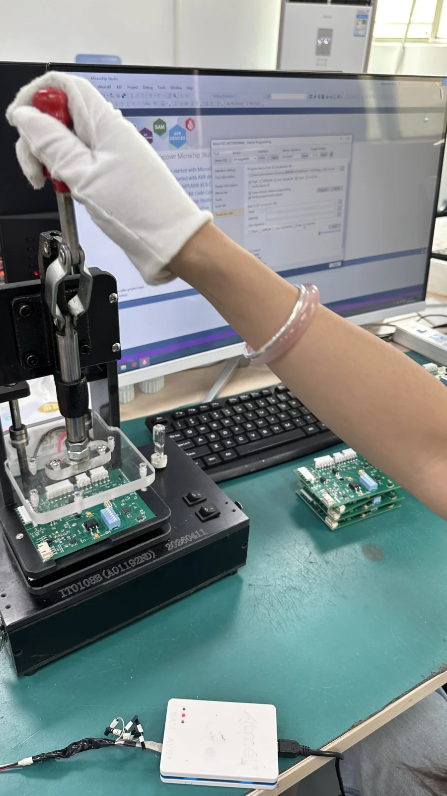
Offline Devices or Programming Access on the PCB
The physical route determines how the programmer reaches the device. FLJ supports programming the IC before placement and in-circuit programming after it is fitted to the PCB.
Offline device programming
The unmounted IC is programmed through a suitable socket or adapter, then prepared for assembly. This can suit a build with an established firmware release or a device that is difficult to reach after placement.
- Unmounted device
- Program & verify
- PCB assembly
The socket or adapter must match the exact device and package. Programmed parts then retain their identification as they are prepared for placement in the specified assembly.
In-circuit programming
Firmware is loaded through an accessible connection on the assembled board. The interface follows the device and board design; access may be provided by a connector, test pads or a project-specific fixture.
- PCB assembly
- Connect the board
- Program & verify
In-circuit programming can sit alongside board checks or later configuration. Supply, reset, connection orientation and access to the relevant signals are part of the board-level setup.
Illustrative process positions. The manufacturing plan defines the actual operations and checks.
| Production question | Offline device programming | In-circuit programming |
|---|---|---|
| What provides the connection? | A socket or adapter matched to the unmounted IC. | Access to the fitted device through the PCB. |
| Where is a firmware change handled? | Review programmed component stock and whether devices can be reprogrammed. | Review board access and whether the device’s current settings allow an update. |
| How does it join verification? | Device programming is followed by the agreed assembly and board checks. | Programming can be arranged alongside the board’s test sequence. |
On a small screen, scroll across the table to compare both routes.
The production cycle includes connection, device handling, writing and verification. Data size affects only part of that cycle; setup and access remain relevant when the build quantity changes.
The Released Image and Target Memory Map
The programming job combines a target device, a released file and a memory or configuration map. FLJ’s scope includes HEX, BIN and S19 files, with tools such as ST-Link Utility, J-Flash and OpenOCD selected for the supported device and connection.
Programming can join PCB assembly, component supply and product-specific testing. The fitted hardware, firmware release and next test operation determine where loading takes place in the build.
Both prototype and production projects can include firmware loading. Firmware development is a separate task and can be discussed through our design and engineering service.
Boot Settings, Protection and Unit-Specific Data
Prepare the settings the device needs
Boot settings, configuration values and code protection can be programmed alongside the application image. Their permitted values and order of application follow the device’s supported programming method and the released product configuration.
Read protection can remove the access needed for verification or a later update. The sequence therefore completes the required data checks before access is restricted, where that device and selected protection method require it.
Recovery behavior is device-specific. ST, for example, documents flash erasure during some transitions from a protected state to a less restricted state. The selected settings must account for the product’s intended update or recovery route.
Technical background: ST guidance on readout protection.
Separate file handling from device protection
Firmware-file confidentiality and a device’s access restrictions protect different things. An NDA can be discussed for customer files; on-device protection uses the chip’s supported features and the specified product settings.
Discuss product-specific data
A serial number, calibration value or other unit-specific field needs a defined source, storage location and programming or test method. Batch-common values and per-unit data are separated when this work is included in the quoted scope.
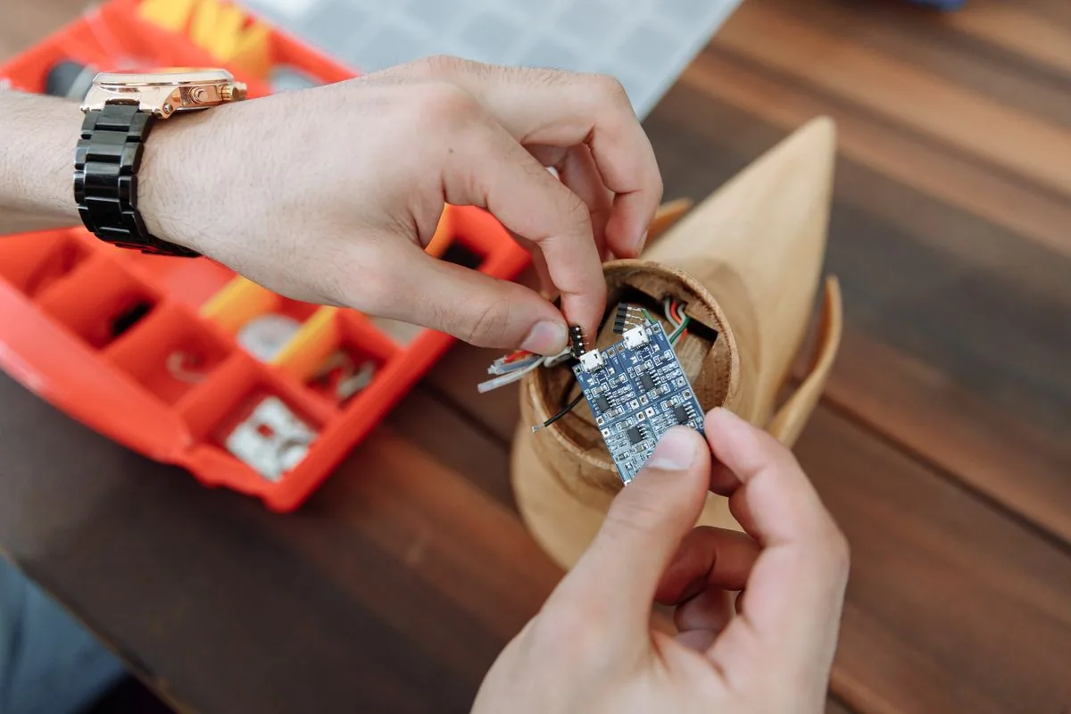
Memory Verification and Product Function
Selecting the right input file, verifying programmed memory and exercising the finished board are three different checks. Each answers a specific question and belongs in the appropriate stage of the programming and test sequence.
| Question | What the check addresses | Useful context |
|---|---|---|
| Which release is selected? | Identify the intended firmware file and programming configuration. | Release identifier, target device, hardware applicability and, where used, a file hash. |
| Was the target programmed as intended? | Verify the relevant memory and device settings using the supported method. | Programmed regions, comparison or checksum method, configuration and protection state. |
| Does the assembly perform its specified functions? | Exercise the board against its product-specific test procedure. | Power, interfaces, inputs, expected responses and the agreed acceptance limits. |
On a small screen, scroll across the table to read all three columns.
Check the written data in its actual context
The tool can compare programmed data or use a supported checksum or CRC method. The job defines the regions covered. Verifying the application image does not necessarily compare every byte of device memory.
A file hash identifies the input file; it does not read the IC. An application’s version response likewise does not compare every programmed region. The selected target, verification method and covered regions are recorded together.
Connect programming with product verification
Memory verification checks the programmed data or settings. A power-up, communication or functional test exercises the board under specified conditions. Our PCB and PCBA testing service covers those product checks.
Discuss the programming results and release identifiers your receiving team needs. Batch or unit identification and the reporting format can be reviewed with the project; acceptance and traceability explains the wider record framework.
Technical background: SEGGER J-Flash documentation and ST programming and verification documentation. Their device and tool conditions apply.
Preparing and Repeating the Programming Job
Once the route is selected, the initial programmed result establishes the setup used for repeated devices or boards. The operations below connect a released package to that production setup.
Review the device and release
Identify the exact device, board revision and firmware release. Product variants and any settings that differ between them are separated before a repeated programming job is prepared.
Prepare the programming setup
Prepare the supported tool, connection and memory locations. Device settings and additional data are entered as explicit job parameters rather than inferred from the firmware file name.
Check the initial programmed result
Check the initial result with the method supported by the target. A first-article or customer sample confirmation can be included before the same setup is repeated across the build.
Run the agreed build and handoff
Repeat programming uses the confirmed configuration and passes the device or board to its next assembly or test operation. Firmware or hardware changes trigger a check of the affected programming setup.
Send Your Device and Firmware Information
Send the exact device part number, hardware revision and the firmware or programming information available. Include quantity and the intended loading stage: loose devices, assembled boards or an existing repeat build.
The first response can identify device support, connection access and the remaining image or configuration information needed for the programming scope.