
POLYIMIDE · FROM MATERIAL TO CIRCUIT
Polyimide PCB
Materials &
Manufacturing
Heat-resistant insulation. Flexible films. Rigid multilayer possibilities.
FLJ manufactures polyimide-based flexible, rigid-flex and rigid circuit boards. Match the material form to your thermal conditions and mechanical design, then turn that construction into prototype or production boards, with assembly available.
Get a Polyimide PCB Quote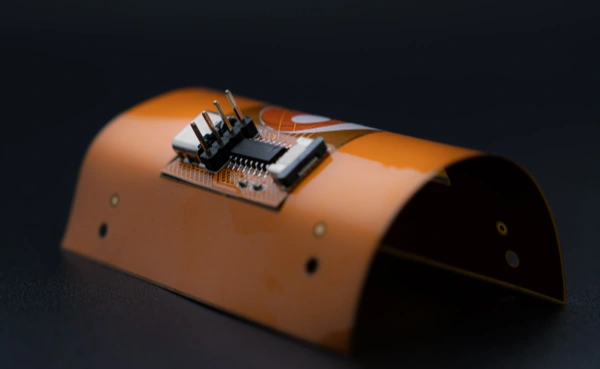
UNDERSTANDING THE BASE MATERIAL
What is polyimide
PCB material?
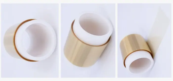
Polyimide, or PI, is a family of polymers used as an insulating material in printed circuits. In a flexible circuit, a thin PI film supports the copper conductors. In a rigid polyimide board, a reinforced resin system forms the solid laminate. The same material-family name therefore covers very different board constructions.
A complete circuit also includes copper and may include bonding adhesives, protective coverlay and local stiffeners. These layers work together: the properties of a bare PI film do not describe the whole finished board.
PROPERTIES WITH A PRACTICAL PURPOSE
Why choose polyimide?
Thermal endurance where the circuit needs it
Repeated soldering exposure and elevated service temperatures place different demands on an insulating material. PI offers options for both: films that remain useful through flex-circuit assembly and reinforced resin systems developed for thermally demanding multilayers. In the latter, resin expansion and stability also matter to the plated connections running through the board.
The useful comparison is between a grade’s thermal properties and the expected exposure. Tg describes a material transition; long-term temperature performance has its own ratings. A heat-resistant substrate also needs a separate heat-spreading strategy—copper, thermal paths and the enclosure still carry heat away from components.
Thin insulation that follows the mechanical design
PI film places electrical insulation in a thin, lightweight structure. Combined with patterned copper, it makes a circuit that can fit around a housing or connect sections at different orientations. That is useful when a rigid board and a separate cable occupy too much space.
The bending behavior belongs to the full stack: copper type and thickness, film, adhesive, coverlay and bend geometry all contribute. A glass-reinforced PI laminate has a different role, giving a rigid circuit its dimensional support.
Insulation and the signal path
A thin PI dielectric separates conductors without adding the bulk of a rigid substrate. That makes it useful in closely packed flex connections. For controlled-impedance routing, its thickness and dielectric constant work together with trace width and reference-plane spacing to set the transmission-line geometry.
Dielectric loss is a separate selection factor. Material data at the relevant frequency helps distinguish a suitable signal-carrying construction from one chosen primarily for thermal endurance; “polyimide” alone is not a low-loss specification.
Material behavior in the working environment
The environment reaches more than the base film: coverlay, bonding layers and exposed contacts are also part of a flexible circuit. Chemical compatibility is therefore selected for those materials and the expected exposure together. Moisture absorption matters during storage and before heat processing, so material-specific conditioning and drying are part of preparing a PI board for assembly. The resin-family name gives a starting point; the complete construction determines the usable combination.
FILM · COPPER-CLAD BASE · REINFORCED LAMINATE
Choose the material form first
PI film and flexible
copper-clad laminates
An adhesive-based flexible laminate bonds copper to PI film with a separate adhesive layer. An adhesiveless base joins copper and PI without that separate layer, changing the dielectric thickness and the interfaces in the construction. Coverlay may still use adhesive even when the copper-clad base is adhesiveless.
Removing the separate base adhesive can reduce the dielectric buildup and remove one interface from the copper-to-film construction. The useful choice depends on the required thickness, thermal exposure and flexing behavior, alongside the copper and coverlay. This is a construction choice, not a count of the finished board’s copper layers.
Adhesive-based
CopperSeparate adhesivePI filmAdhesiveless base
CopperPI filmConceptual base construction, not to scale. Coverlay and other finished-circuit layers are not shown.
Reinforced PI cores
and prepregs
Rigid PI multilayers use copper-clad cores and matching bonding materials. The core supplies a cured dielectric and copper for the inner circuits; prepreg flows and cures during lamination to join the patterned layers.
A named rigid-board example is Isola P95 laminate with P25 prepreg: an E-glass-reinforced polyimide/thermoplastic blend. Its product data illustrates why separate material ratings matter.
| P95 / P25 property | Listed value | What it describes |
|---|---|---|
| Glass transition, DSC | 260°C | A material transition, not a board operating limit |
| Relative thermal index, UL 746 | 170°C | Long-term thermal endurance rating |
| Flammability | UL 94 HB | The classification of this material system |
These values describe the named material. A different PI formulation can have different thermal, electrical and flame properties.
Isola P95 / P25 material information provides the underlying product data.
SELECT THE CONSTRUCTION FOR THE JOB
Polyimide vs FR-4
| Selection question | Polyimide option | FR-4 option |
|---|---|---|
| Mechanical form | PI film serves flexible connections; glass-reinforced PI serves rigid boards. | Standard glass-reinforced FR-4 serves rigid boards. |
| Thermal duty in a rigid board | Reinforced PI grades offer thermal endurance options for demanding builds. | Standard and high-Tg grades cover many assembly and service conditions. |
| What does the signal need? | Use grade-specific Dk and Df with their test conditions. | FR-4 also varies by grade; compare the actual loss and geometry needs. |
| What controls the finished cost? | Material system, construction and processing route all contribute. | Established rigid-board materials are often the economical starting point. |
For a rigid board, compare reinforced PI against the relevant FR-4 grade, rather than comparing bare PI film with a complete fiberglass laminate. Where heat exposure is the main concern, high-Tg PCB materials are also worth evaluating before changing the resin family.
MATERIAL CHOICES IN FINISHED HARDWARE
Polyimide in finished circuits
Flexible connections
and rigid-flex assemblies
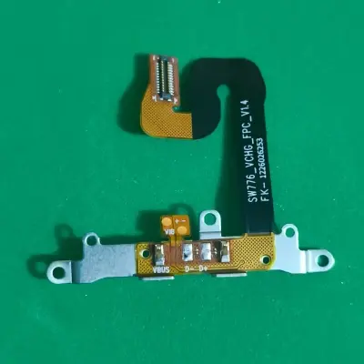
A flexible circuit carries copper conductors through a thin insulated span. This can connect a compact device’s control board to a display, sensor or connector while fitting the available enclosure space. Local support can keep a component or contact region firm while the interconnecting section bends.
When rigid component-bearing sections and flexible interconnects belong in one board, rigid-flex construction integrates those regions. For separate flexible circuits, flex PCB manufacturing covers the contact, coverlay and stiffener options in more detail.
Rigid PI for thermally
demanding electronics
Glass-reinforced PI can support multilayer circuits in industrial and instrumentation electronics where the material’s thermal behavior is part of the selection. Its role is to support and insulate the circuitry through the specified manufacturing and service conditions.
Fabrication begins with imaging and etching the inner copper circuits. PI cores and compatible prepregs are laminated with a cure cycle suited to that resin system. Drilled holes are prepared and metallized to connect the intended copper layers. The material choice therefore carries through into bonding and interconnect production, rather than remaining a label on the drawing.
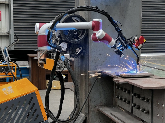
Application photographs illustrate hardware categories; they do not identify a laminate grade or a customer project.
FLJ supplies PI-based boards as flexible circuits, rigid-flex assemblies and rigid multilayers. The order can include the specified film or laminate, copper construction, coverlay or solder mask, contact finish and final outline. Material identity, buildup and finished features are carried from the prototype into repeat production.
For populated boards, PCB assembly adds component mounting and soldering to the fabricated circuit. Send the board files, material designation or required material properties, quantity and assembly scope to start a quotation.