
Metal Core PCB
Manufacturing
Thermal management starts at the circuit board.
FLJ manufactures metal core PCBs for LED lighting and power electronics, with aluminum and copper constructions, custom profiles and optional component assembly. Order prototype quantities or production boards built to your circuit and mounting arrangement.
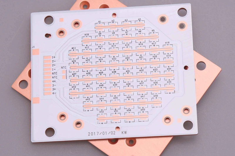
Metal Core PCB Construction and Thermal Performance
A metal core printed circuit board combines the electrical circuit with a metal heat spreader. In the common insulated metal substrate (IMS) construction, a thin dielectric bonds the copper circuitry to an aluminum or copper base.
An LED array operating for long periods needs a continuous route for heat to leave the packages. Heat moves through the soldered pads, across the insulating layer and into the metal beneath them. The base spreads it over a wider area for transfer to a heatsink or housing. This path helps control LED junction temperature and preserve light output during operation; it also carries heat away from power semiconductors.
The dielectric is central to this arrangement: it must conduct heat while electrically separating the live circuit from the metal. LED-board constructions commonly use dielectric thicknesses around 75–150 μm (3–6 mil). A thinner layer shortens the heat path; the material’s insulation properties determine the suitable thickness for the circuit.
Thermal conductivity, expressed in W/m·K, describes a material. Dielectric thickness, heat-transfer area and the mounting interface also affect thermal resistance. Keeping these quantities distinct matters when choosing a metal base: high conductivity in the base cannot compensate for a poor insulating bond or incomplete contact with the heatsink.
Circuit copper thicknessSets the conductor cross-section and contributes to current carrying and local heat spreading.
Dielectric thicknessSets the distance heat crosses while maintaining separation from the metal.
Base thicknessContributes to rigidity, mounting fit and heat spreading across the board.
Aluminum, Copper and Multilayer Metal Core PCBs
The right construction connects the heat source, routing layout and cooling surface. Base material and circuit copper are separate choices: a copper base is not the same feature as thick copper traces.
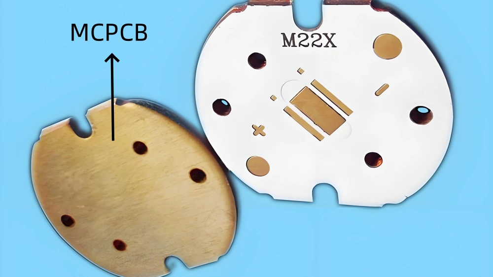
Aluminum-base boards
Aluminum PCBs combine low weight with practical heat spreading and production cost. They are widely used in lighting modules mounted against a fixture body or extruded aluminum profile. Aluminum alloys such as 5052 and 6061 are used as base materials, with the selected grade and thickness matched to the mechanical construction.
Copper-based boards
Copper-core PCBs offer higher base-metal thermal conductivity for spreading concentrated heat from high-power devices. Copper is heavier and more expensive than aluminum and requires more demanding machining. Copper grades such as C1100 are used where the thermal and mechanical design justify that trade-off. Aluminum is often chosen for broad LED-board areas, while copper can be useful beneath a concentrated heat source in a compact assembly.
Metal Core PCB vs. FR4
A small number of low-power indicators may need no special substrate. An array of LEDs running for long periods creates a different thermal task: heat has to leave many closely spaced devices throughout operation. Metal-base construction becomes useful when that load needs a short path toward a cooling surface.
| Feature | FR-4 PCB | Single-layer metal-base PCB |
|---|---|---|
| Board structure | Glass-reinforced epoxy with copper circuits and planes | Copper circuit, thermally conductive dielectric and a metal backing |
| Heat-transfer path | Copper areas and thermal vias can carry heat toward another surface or heatsink | Heat crosses the thin dielectric directly into the metal base |
| Thermal vias | Can connect device thermal pads to copper on other layers. Open vias in those pads may draw solder away during assembly, so their treatment matters. | Not required to create the direct dielectric-to-base heat path |
| Components & holes | Surface-mount and through-hole components; plated vias between layers | Normally SMT components with mechanical mounting holes; electrical holes through metal need an insulated structure |
| Mask & cooling surface | Mask may cover both circuit faces | White mask is common on the LED circuit face; the metal underside forms the mounting/cooling surface |
| Mechanical processing | Standard laminate drilling, routing and scoring | Metal cutting and edge finishing require suitable tooling and burr control |
Choose FR-4 PCBs for their broad routing and material options when the thermal design permits. Choose a metal-base construction when the board needs to spread heat directly toward a heatsink or housing. Multilayer metal-core boards combine different features and need their own construction assessment.
Metal Core PCB Manufacturing and Assembly
The circuit pattern follows familiar PCB principles, but a conductive metal base changes the hole structure, mechanical processing and assembly heat flow. FLJ fabricates the board around those differences.
Fabricating the insulated circuit
The copper, dielectric and metal base form the starting laminate or bonded stack. For multilayer constructions, lay-up and lamination also establish the internal routing and insulation. The dielectric must bond continuously to the surrounding surfaces: voids interrupt heat transfer and can weaken electrical isolation.
Imaging and etching define the tracks, pads and copper areas. Copper thickness affects etch compensation and achievable spacing. The finished pattern is inspected before solder mask and pad finish are applied.
Forming holes through a metal core
A conventional single-layer SMT board can be drilled for mechanical mounting without a plated-through-hole process. It does not need hole-wall metallization simply to move heat into its backing.
For an electrical connection through a conductive core, the conductor must be separated from the metal. One route creates an oversized clearance, fills it with insulation, then drills and metallizes the smaller electrical hole. This adds operations that a simple mounting hole does not require.
Machining and finishing the metal base
Routing, drilling and profile cutting create the mounting features and finished outline. Tool condition and cutting parameters control burrs and damage near the dielectric. Clean edges and an accurate profile help the board seat against its cooling surface.
Solder mask protects the circuit; white is a common choice for LED light engines. ENIG, immersion silver, immersion tin and OSP are finish options within the aluminum-board process range. Final checks cover circuit continuity, shorts, dimensions and the specified circuit-to-base insulation test.
Assembling components on the board
FLJ can supply the populated board through SMT assembly, bringing solder-paste printing, component placement and reflow together with fabrication. Because the metal base draws heat away from the soldering area, the temperature profile must heat the component joints adequately across the assembly.
The soldering profile is developed around the base material, board dimensions and component mix. Inspection checks placement and solder-joint quality, with electrical or functional testing included for the populated build. Fabrication and assembly remain connected through the same board construction.
Metal Core PCB Manufacturing Specifications
FLJ supplies aluminum and copper-based boards within the following fabrication ranges. Finished-board thickness, circuit copper and the selected thermal dielectric are specified separately.
| Parameter | Aluminum-base PCB | Copper-based PCB |
|---|---|---|
| Finished-board thickness | 0.2–5.0 mm | 0.5–5.0 mm |
| Finished circuit copper | 18, 25, 35 or 70 μm | 1–3 oz |
| Construction | Single-layer metal-backed and selected custom structures | 1–8 layers; single-sided, double-sided with core, multilayer and thermal-separation |
| Dielectric conductivity | 1–12 W/m·K, depending on material grade | Selected with the insulation and thermal construction |
| Conductor geometry | Minimum spacing: 0.2 mm | Line / space: 4 / 5 mil at 1 oz; 6 / 8 mil at 2 oz; 10 / 11 mil at 3 oz |
| Board size | Standard maximum: 480 × 580 mm Large-format option: 580 × 1180 mm | Maximum: 1200 × 480 mm |
| Hole specification | Hole tolerance: ±0.1 mm | Minimum drilling hole: 0.6 mm |
| Outline tolerance | ±0.15 mm | CNC: ±0.15 mm; punching: ±0.1 mm |
| Surface finish | ENIG, immersion silver, immersion tin, OSP | Finish specified for the copper-based construction |
Available combinations follow the board construction and material. Additional dimensional details are listed in our metal-core PCB capabilities.
Metal Core PCB Applications
LED light engines are a major application, from linear luminaires to high-power arrays. Metal-base boards are also used beneath heat-generating semiconductors in power electronics.
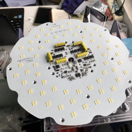
Industrial & outdoor LED lighting
Streetlights, high-bay luminaires and floodlights operate groups of LEDs for extended periods. The board carries the LED array and transfers heat toward the fixture’s heatsink. Pad layout, mounting holes and the metal contact surface work together within the optical and mechanical design.
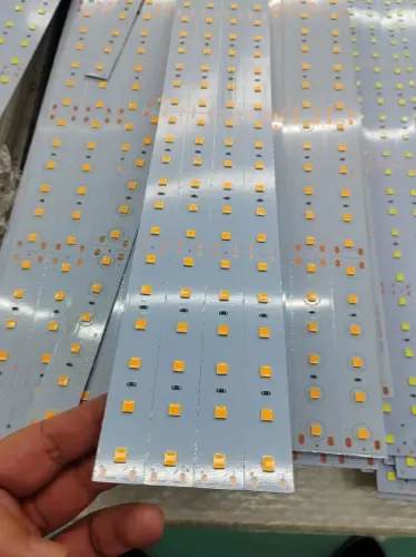
Commercial & architectural lighting
Linear fixtures, downlights and display lighting fit their circuits into shallow housings or long aluminum profiles. Metal-backed strips bring the LEDs close to that cooling surface. Board straightness, mounting pitch and consistent underside contact matter when several modules share one luminaire.
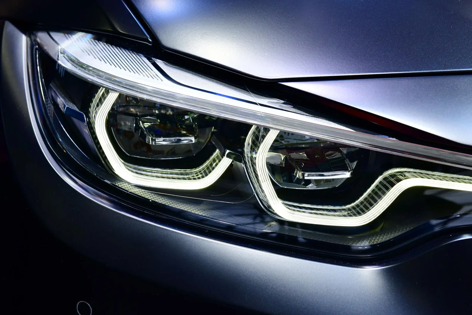
Automotive LED lamps
Headlamps, daytime-running lights and signal lamps place LED heat sources inside compact housings. The board provides a path into the lamp’s cooling structure while locating the LEDs relative to the optics. Thermal cycling, dielectric insulation and mechanical attachment are part of the material and assembly design.
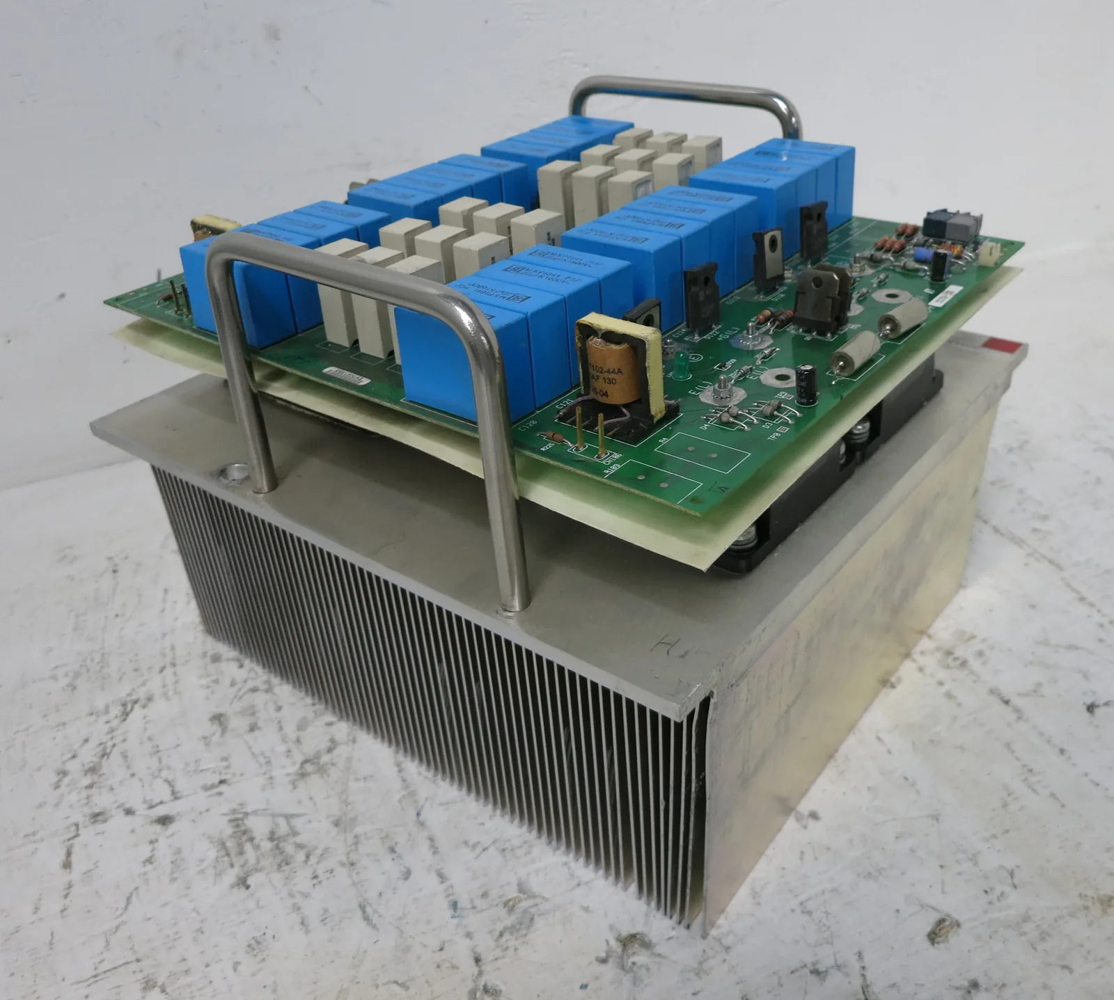
Power conversion & motor drives
MOSFETs, rectifiers and other power devices generate heat during conduction and switching. A metal-base board spreads that localized load toward a chassis or heatsink. Circuit copper carries the current, while the insulating structure separates live conductors from the cooling base; compatible thermal-separation constructions provide an additional option.
Order bare boards or a complete assembly
Send the circuit files, board outline and quantities for a metal-core PCB quotation. FLJ can combine fabrication with PCB assembly, supplying prototype builds and production quantities through the same project.