
SMT & PCB Assembly Equipment
From solder paste to inspected assemblies, our production resources support a connected build process. Seven SMT lines, two DIP lines and two manual soldering lines help us prepare the assembly route around your product.
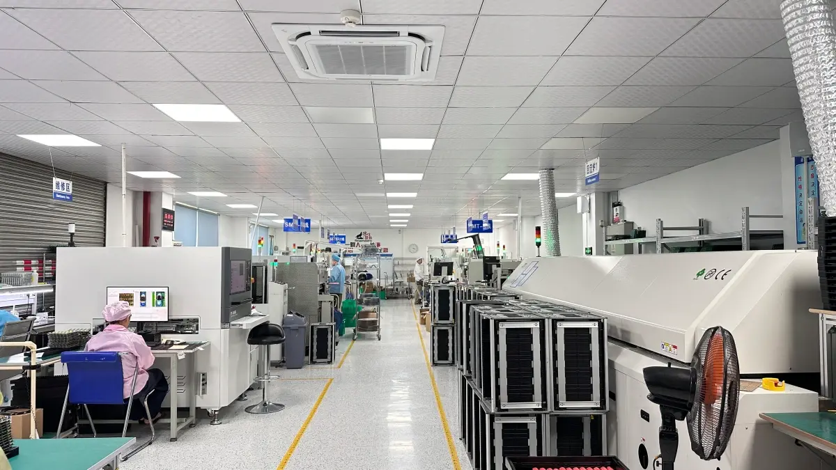
Assembly resources and their role in your build
SMT equipment places surface-mount components onto prepared circuit boards. The surrounding process—printing, inspection, soldering and verification—is what turns placement into a usable electronic assembly.
These resources work with the approved BOM, board data and process instructions. Package mix, board construction, panel layout and the intended test coverage guide the actual production route.
| Resource | Published configuration or method | Manufacturing role |
|---|---|---|
| SMT production | Seven lines; Yamaha YRM20 placement resources | Surface-mount component placement |
| Paste preparation | Automatic stencil printing | Apply solder paste to the intended pads |
| Paste inspection | 3D SPI | Review deposits before component placement |
| Reflow | Controlled temperature and conveyor settings | Form solder joints for the selected assembly |
| Through-hole assembly | Two DIP lines and wave-soldering resources | Assemble inserted components and connectors |
| Manual soldering | Two manual soldering lines | Complete product-specific assembly work |
| Inspection | AOI and X-ray | Review visible features and selected hidden joints |
Printing and solder paste inspection
Stencil printing prepares the paste deposits that support subsequent solder joints. Alignment, stencil openings and print settings are reviewed around the pad geometry and component mix, especially where the assembly includes fine-pitch or tightly spaced features.
3D solder paste inspection provides process feedback before placement. Reviewing deposit conditions at this stage helps address printing issues while the build is still in preparation, instead of relying only on inspection after soldering.
Our team can review panel features, fiducials and assembly data with your available files. If information is missing, we discuss it with you as part of preparing the build.

Placement and controlled soldering
Yamaha YRM20 placement resources support our SMT assembly operation. Placement preparation connects component identity, feeder setup, footprint information and position data with the intended BOM configuration.
Reflow preparation considers the solder materials, component requirements and thermal behavior of the assembly. Temperature and conveyor settings are managed as part of the process, with the chosen route reviewed for the board and package mix.
For new designs, a first-article review can help confirm component identity, orientation and assembly details before the remaining production quantity. We discuss any customer approval point alongside the production plan.
Through-hole and mixed-technology assemblies
Connectors, power parts and other inserted components can require a through-hole route alongside SMT production. Two DIP lines and two manual soldering lines support this part of our assembly scope.
Wave soldering, manual work and assembly fixtures are selected around the product’s components and mechanical constraints. Mixed-technology builds may move through several stages, with the sequence planned to protect completed work and give the inspection team access to the relevant features.
Placement, handling and rework resources
Equipment supports the agreed assembly process. We connect placement, soldering and inspection around the released board and component data.
| Feature | Process reference | How it applies |
|---|---|---|
| Placement resource | Yamaha YRM20 | FLJ’s assembly page publishes equipment accuracy ±0.025 mm; board/package acceptance is reviewed separately |
| Package scope | BGA, WLCSP, QFN, POP | Match the device and stencil with support and inspection |
| BGA rework | Published specialized assembly support | Review removal/replacement and hidden-joint inspection for the board |
| Board handling | Panel, carrier and component-clearance review | Outline, board thickness and component height determine the setup |
| Production planning | Line resources matched to the approved build | Quantities, sourcing and assembly complexity establish scheduling; equipment speed alone is not a delivery estimate |
Inspection, programming and the final handoff
AOI reviews visible assembly features, while X-ray supports selected hidden-joint inspection. Electrical and functional testing then address the checks defined for the circuit or product. These methods provide different information and can be combined into a useful verification plan.
IC programming and further product assembly can also be included in the manufacturing package. Share the firmware, test ideas or drawings you have, and we can help define the fixtures, instructions and records needed for the next stage.
For a factory or supplier review, tell us which production areas you want to discuss. We can connect the equipment conversation with the construction, package requirements and planned quantities of your actual project.
Frequently asked questions
What SMT placement equipment does FLJ PCB list?
Our published factory information lists Yamaha YRM20 placement resources as part of an operation with seven SMT production lines.
Can the same build include SMT and through-hole parts?
Yes. Our assembly scope includes mixed-technology builds, using SMT, DIP and manual soldering resources around the product’s component and mechanical requirements.
Can we discuss the assembly route before all files are complete?
Yes. Send the board information, BOM and questions you have. Our team will review the available package and follow up on the details needed to prepare production.
Explore related capabilities
Let’s review your next build
Send your available board files, drawings or project questions. Our team will review the information and follow up with you about the next step.