
EV Charger PCB Manufacturing & Assembly
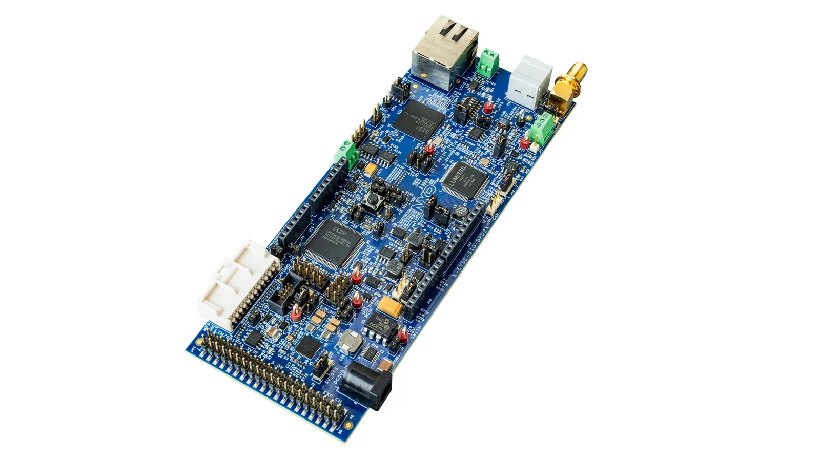
· Supplier example.
Circuit boards and assemblies for charging control, communication and power interfaces.
FLJ combines PCB fabrication, component sourcing and assembly for EV charging equipment. Order bare boards, populated PCBAs or a build completed with the specified internal wiring and mounting parts.
Prototype and production builds, with applicable firmware loading and product-defined electrical or functional checks.
Boards for AC EVSE and DC Chargers
FLJ manufactures bare boards and assembled PCBAs for charging control, communication, metering and power interfaces. The board’s role determines the components, connections and assembly work supplied.
AC Charging Control Boards
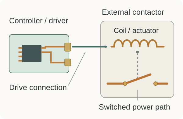
AC EVSE controls and monitors the AC supply connection to the vehicle, whose onboard charger performs the main battery-charging conversion. Its electronics can combine auxiliary power, communication, metering connections and switching control. In the external-contactor arrangement shown, a board output drives the coil while separate contactor contacts carry the switched power path. The drive circuit and the charging-current path therefore have different connections and assembly requirements.
We build the control and interface circuits to the supplied design, fitting the specified devices and connectors. The selected board can form one part of a larger charging assembly with separate communication, metering or power hardware.
DC Charger Control and Interface Boards
A DC charging station contains the offboard conversion stages that produce its charging output. Control and interface boards connect commands, measurements and status signals to those stages. FLJ manufactures and assembles the selected control, communication and power-interface boards; builds containing the conversion hardware can also use our power-electronics PCB manufacturing and assembly services.
Manufacturing and Assembling Charger Electronics
FLJ combines board fabrication, component supply and assembly around the controller’s actual pads, holes and external connections. The finished construction and fitted parts must match the same circuit and mechanical drawings.
Board Construction and Electrical Separation
Imaging and etching form copper tracks, pads and clearance areas. In a conventional through-hole multilayer build, the patterned inner layers are aligned and bonded with insulating material before drilling and hole metallization connect the required layers. The selected outer-layer process forms the finished surface features that receive the components. Copper geometry, bonded insulation and plated interconnections each have a different role in the completed board.
We fabricate the specified slots, cutouts and finished holes around the control and interface circuits. During assembly, component positions, solder and mounting hardware must preserve the drawing-defined separation areas. Connector pads, lead holes and mechanical features are kept consistent with the parts and installation they support.
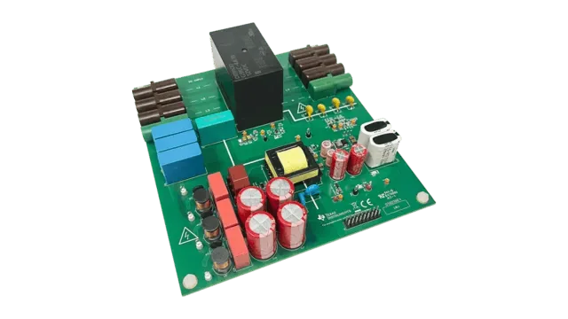
· Supplier example.
SMT Components, Relays and Terminals
The BOM identifies the controller, interface devices, passives and connector packages to be fitted. FLJ can combine specified component sourcing with customer-supplied parts. Our SMT assembly process deposits solder paste, places the devices in their required orientation and forms component-to-pad joints during reflow.
Where the design uses leaded relays, terminals or headers, we seat and support them at the required height with access to their solder joints. Connector orientation and mechanical seating matter at the subsequent cable interface. The mixed SMT and through-hole assembly sequence follows the actual component mix, solder access, board construction and heat exposure.
Wiring, Mounting and Board Protection
For a build that includes internal connections, FLJ fits the board-to-harness connections to the specified pin map and connector keying. Cable exits and branches must clear fasteners and leave mating points reachable. Routing, support and strain relief reduce the loads transferred to board terminations during handling or movement.
Our assembly integration can include the board supports, internal wiring and mounting parts. We align the board and its connectors with the product’s supports and openings, then follow the fastening arrangement while keeping the harness seated and accessible. Delivery can stop at the PCBA or include this specified installed scope.
Where conformal coating is specified, the coverage drawing defines the circuit areas to protect and the contacts that must remain usable. Masking and application follow that boundary, including any connector solder side to be coated and the mating, programming or test surfaces to retain in their required condition.

· Supplier example.
Programming and Charging-Interface Testing
Assembly inspection checks the fitted parts and their connections. A powered controller check then applies a product-defined input and observes the selected board response with the required supply, configuration and operating state.
Released Firmware and Controller Configuration
For boards that require programming, we load the released firmware or configuration applicable to the target hardware. File identity establishes the selected input; supported programmed-memory comparison checks stored content. A subsequent operating check observes how that configured board responds. These checks remain tied to the same hardware and release.
Defined Inputs, Switching Feedback and Status
For a controller with a contactor-drive interface, a board-level check can apply the prescribed enable input or command and measure the response at the designated drive terminal. FLJ performs the selected functional checks against the product’s test criterion. The setup identifies the supply, controller state, input, connection and measurement point used for that result.
If the procedure includes fixture-simulated feedback, the record identifies the injected state and the controller’s resulting response as a simulation. Drive-terminal measurements, returned status and physical contact observations are distinct evidence. The product-specific fixture provides the required stimulus and measurement connections.
For repeat builds, the board revision, applicable firmware and test-program revision stay associated with the selected results. Where delivery includes internal wiring or installation, the required checks can follow the completed connection path.
Send the PCB files, BOM, assembly drawings and required delivery level. Include the applicable firmware and test requirements so fabrication, assembly and checks can be scoped together.