
LED PCB Manufacturing & Assembly
Custom light-source boards, LED strips and driver assemblies for your lighting product. FLJ combines PCB fabrication, component sourcing and assembly for prototype and production orders.
Discuss Your LED PCB Build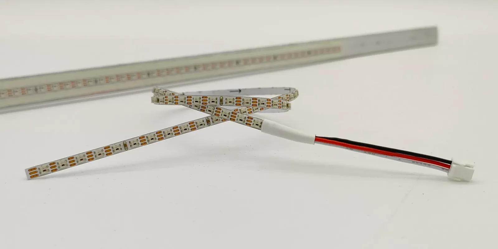
Custom LED Boards and Lighting Applications
FLJ supplies custom bare and populated LED boards for lighting products. Emitter placement, board outline and connection points can be defined around the fixture layout. The scope can include a separate driver or control PCBA when the design calls for one.
Linear fixtures and panels
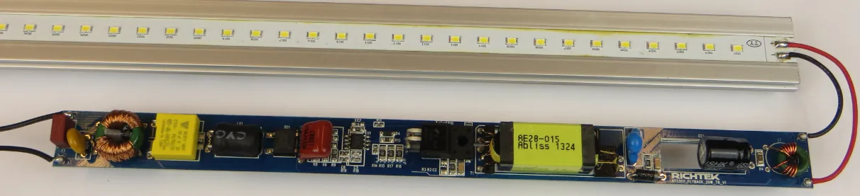
For linear luminaires and panels, LED position and spacing follow the intended illuminated area, while board dimensions and mounting features follow the housing. A straight or segmented board can be specified to fit the fixture space, with electrical connections placed for the installation.
Compact arrays and shaped modules
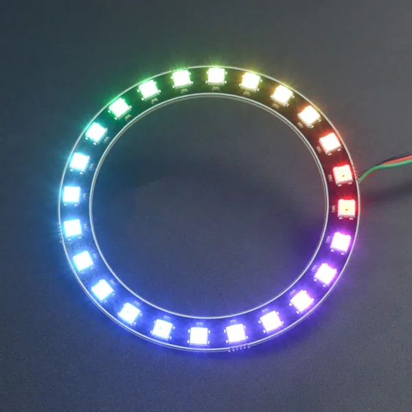
Compact arrays place emitters around the required opening or illuminated area. Circular and other shaped boards combine that pattern with fixing features and connection lands, so the light-source assembly fits the fixture’s mounting surface.
The light-source board carries the emitters and their electrical paths. A separate driver or control PCBA supplies power regulation or dimming functions. FLJ supplies bare boards or populated light-source and driver assemblies through our PCB assembly services.
Rigid and Flexible LED Strip PCBs
Rigid linear boards
A rigid linear board holds LED rows in a fixed plane for a straight luminaire or panel. Its outline, fixing points and end connections locate the light source within the housing; the mounting surface provides the intended support.
Flexible strip circuits
FLJ combines flexible circuit fabrication with assembly of the selected LEDs. Film, patterned copper and protective openings form the strip, with local reinforcement at connections where needed. The installed path keeps bending in the intended regions; a repeatedly moving design needs a construction and evaluation matched to that motion.
Read the strip specification
A strip specification describes the emitter, its arrangement, the circuit and the installed shape. Reading these fields together connects the light-source layout with its power and mounting requirements.
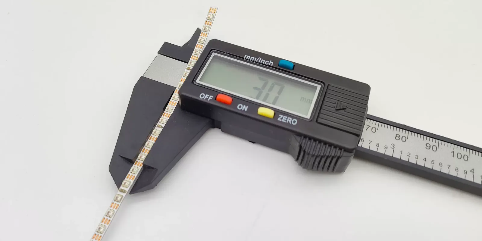
Illustrative layout: a uniformly spaced row of 100 LEDs per metre gives a 10 mm centre-to-centre pitch. This geometric example is separate from the pictured reference strip and its electrical specification.
| Parameter / unit | Meaning / impact |
|---|---|
| LED selection / package | The full manufacturer ordering identity selects the emitter. Its package drawing defines body and terminal geometry; the manufacturer’s recommended land pattern guides the PCB pads. |
| LED count / density (LEDs/m) | Quantity and spacing describe how the LEDs are distributed along the board. LED density is a layout measure; the optical arrangement and drive conditions are specified separately. |
| Supply (V) / current (A) | Input voltage and circuit current belong to the selected electrical design, including its LED strings, driver or current-limiting components. |
| Width / outline (mm) | Board width, profile and connection locations determine fit in the channel, housing or mounting area. |
| Color / CCT (K) | CCT describes the specified white-light appearance. Adjustable-white or RGB operation also needs the corresponding emitters, channels and control circuitry. |
LED PCB Materials and Fabrication
FLJ fabricates LED circuits on FR-4, aluminum-backed laminates, copper-base constructions and selected ceramic substrates. FR-4 provides routing for driver, control and light-source boards where the complete thermal design suits it. The other constructions change the path between the emitter, electrical insulation and the fixture’s cooling surface.
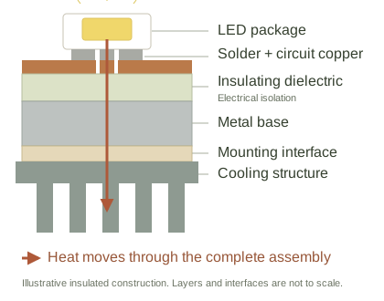
In an insulated aluminum PCB, circuit copper carries the electrical pattern, the dielectric isolates it from the metal base while conducting heat, and the base spreads heat toward the mount. Solder, dielectric thickness and the mounting interface all contribute to the heat path shown here.
Copper-core constructions offer insulated layouts and package-compatible local direct thermal paths. Where a separate emitter thermal contact is used, its geometry and electrical potential must suit the base connection. Solder and mounting contacts remain part of the finished thermal path.
For compact emitter carriers, ceramic PCBs and submounts combine a selected ceramic substrate with patterned conductors, device pads and connection features. Substrate choice, pad finish and assembly support are matched to the carrier design.
Finished Features for the Lighting Layout
Scroll across to read the fabrication details.
| Feature | Fabrication work |
|---|---|
| Copper and pads | Image and etch the circuit pattern in the selected copper build. Form the solder lands for the chosen device footprint and pad finish. |
| White mask on rigid / metal-backed boards | Apply the specified white solder mask around LED pads, keep connection areas exposed and finish the uncovered copper for soldering. |
| Outline and mounting features | Route the profile and form mounting holes or slots to the drawing. Electrically connected holes in a metal-backed build require the appropriate insulation from the base. |
| Artwork, location and panel features | Form the land patterns, fiducials and board reference features. Panel and separation features support positioning and handling through assembly. |
LED PCB Assembly Services
FLJ supplies LED PCB assembly with component sourcing for the specified emitters, driver parts and connections. Full turnkey builds combine board fabrication and component purchasing; partial-turnkey or consigned builds use the identified materials you provide. The complete LED ordering identity carries into the material kit and placement setup.
Specified LEDs, placement and soldering
Our SMT assembly process brings LED polarity, position and rotation into paste printing, placement and reflow. The chosen package defines its lands and any separate thermal pad, where solder amount and component seating affect the connection. Flexible circuits use suitable support during soldering; metal-backed boards change how heat is absorbed and spread. We prepare a measured profile for the actual board and component mix.
Drivers, connections and handling
Driver devices, terminals and other connections are fitted to the specified layout, combining SMT and through-hole work where required. Material preparation follows the selected LED’s storage and exposure requirements. During handling and separation, support and contact locations protect optical surfaces and limit bending loads near mounted components; package-specific soldering and cleaning instructions remain part of the process preparation.
Inspection and Powered Functional Checks
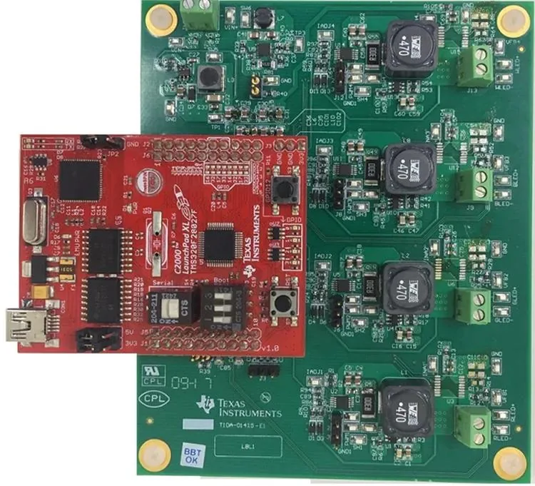
FLJ uses SPI to check paste deposits before placement and AOI to examine visible component position, polarity features and solder joints. Selected X-ray inspection can examine concealed solder features where the view resolves them. Findings lead to review and applicable correction, followed by reinspection. Powered checks then exercise the lighting function.
Light-source boards
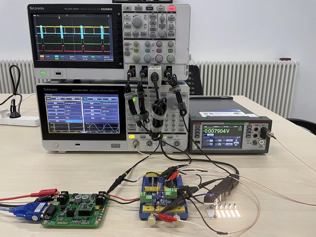
A light-source board is energized with the specified supply and LED-string state. The check observes the intended strings and measures current at the defined point against the product’s limits. On a multichannel assembly, the enabled channel and load state identify which response is being checked. These results describe the board’s electrical operation under those conditions.
Driver and dimming controls
For a driver assembly, the prescribed input and load are applied before checking output current or the required dimming response. A PWM-controlled design, for example, can be checked at defined commands with its intended load connected. Our board-level functional testing follows the product’s measurement points, configuration and acceptance limits.
Bring the light-source board, strip or driver assembly into one manufacturing order. Discuss the board construction and assembled delivery you need.
Request an LED PCB QuoteRelated LED designs and assemblies
Explore the board images, product information and design details for related projects.

RGB LED Strip Board
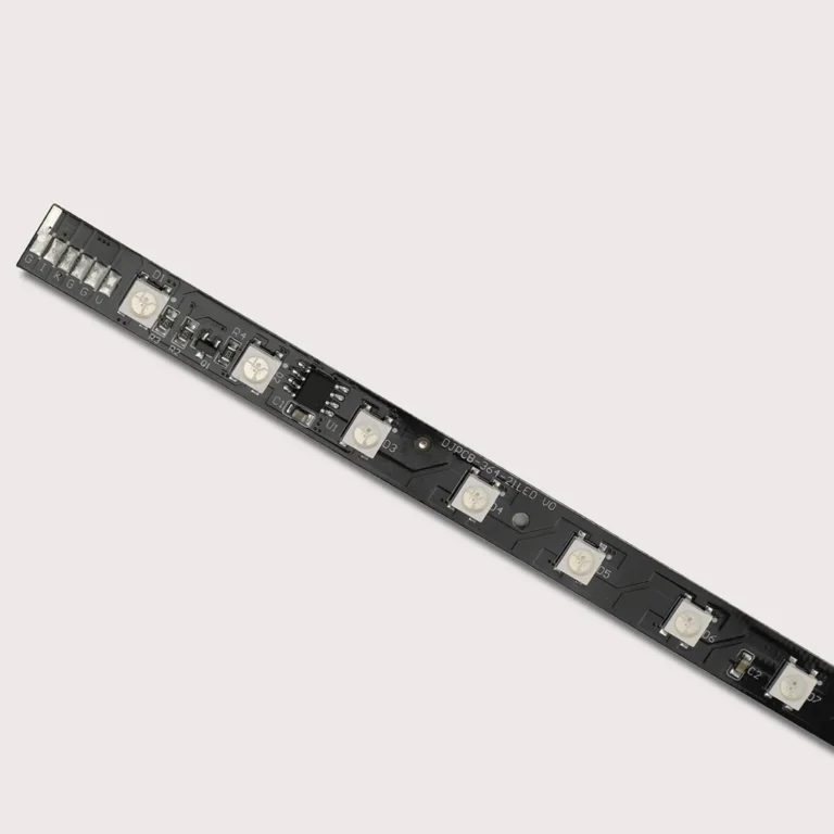
Control-board development and assembly for RGB lighting-strip products, with project review focused on strip layout, lighting behaviour and the power/connection arrangement.
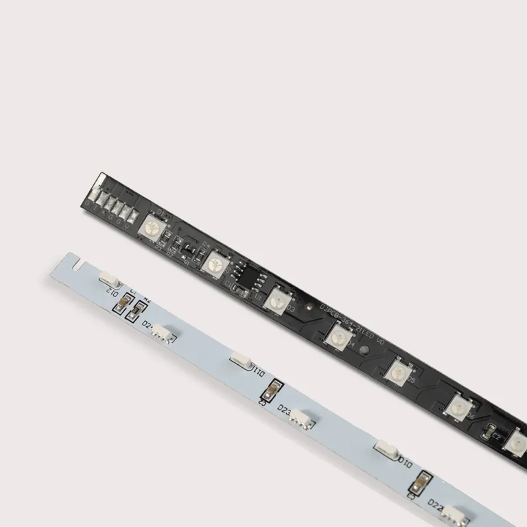
RGB LED Strip Assembly
Control-board development and assembly for RGB strip-lighting products, with project review focused on strip length and arrangement, interconnections and assembly handling.
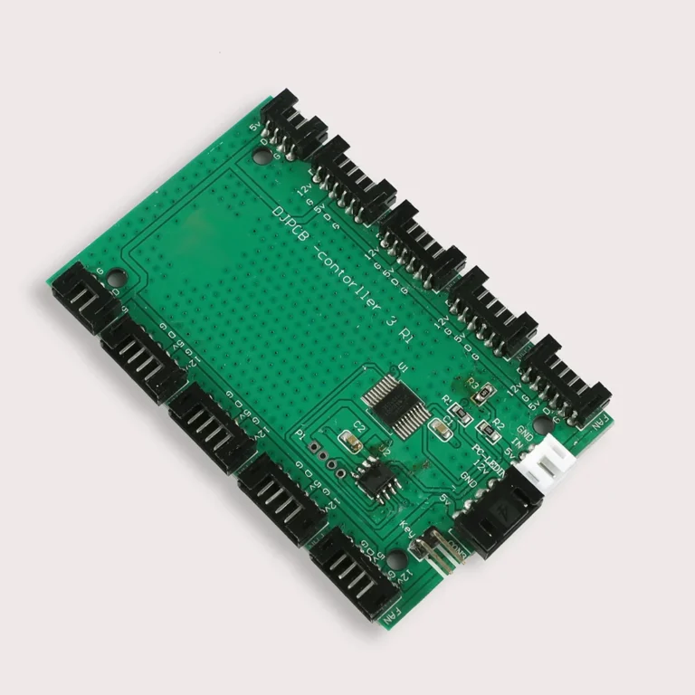
RGB Lighting Control Box Board
Control-board development and assembly for RGB lighting control boxes, with project review focused on lighting connections, board-to-enclosure fit and access to the control interface.