
Semi-Flex PCB Manufacturing
Built flat. Formed to fit your product.
FLJ manufactures semi-flex printed circuit boards with locally thinned FR-4 bending zones. Connect rigid component areas in a compact installed shape, with bare-board fabrication or sourcing, assembly and testing for your project.
Request a semi-flex quote →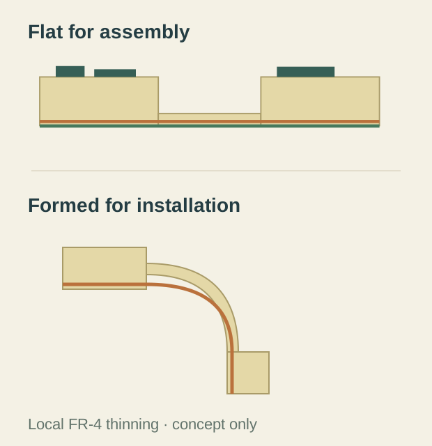
A Rigid PCB That Folds Into Place
Component areas can share one circuit even when their final positions sit on different planes.
A semi-flex board begins as an engineered FR-4 circuit construction. Selected connecting areas are made thin enough for the defined installation bend, while the component regions retain the support of a rigid board. The assembled circuit can then be formed to follow its housing or carrier.
Connect the functions, reduce separate parts
Where the integrated circuit replaces a cable or board-to-board connection, it removes that separate interconnect from the assembly. It can also free the connector space on the connected board areas.
Compact controls, instrument and metering assemblies, sensor connections and access-system electronics are examples of products where a fixed installed shape can be useful. Semi-flex is selected for that installation duty; the connecting zone is not intended to act as a continuously moving hinge.
How the Depth-Milled Bend Zone Works
Controlled-depth milling removes material locally while preserving the intended FR-4 connection and its conductors. The remaining structure gives the board its installation flexibility.

The material left behind
What remains after milling is the section that will be formed. Removing too little can leave a connection too stiff for its intended shape; removing too much can damage the retained material or electrical path. The target is therefore the finished remaining structure, reached from the actual local board thickness and machining reference.
The board thickness, internal construction and reference used during machining establish the cut that produces the target remaining section. Conductor position and the protective coating are included in that construction, so the cut preserves the electrical path.
The path into the installed shape
The length of the thin area and the selected bend geometry work with its remaining thickness. A bend distributed along an intended span behaves differently from a sharp crease at the edge of a rigid region.
Transition shape, local copper layout and the positions of components and holes are selected around the formed connection. Its rigid ends are located and supported in the finished product so the thin section serves the intended connection path.
An identical programmed cut does not guarantee identical remaining thickness if the starting board thickness or surface height varies. Board support, the machining reference and checks at suitable positions across the milled region work together to control the result. Local warpage and thickness variation are considered alongside the tool setting.
From Flat-Board Assembly to the Installed Product
Manufacture and component assembly use the defined flat-board arrangement; installation brings its rigid functions into their final positions. FLJ supplies the bare semi-flex board or carries the project through component sourcing, assembly and testing, with the required delivered state included in the build.
Make and verify the local section
Circuit formation, interconnections and finishing produce the electrical board. The selected manufacturing route incorporates controlled-depth machining of the bending area and protection of the conductors and adjacent surfaces.
Checks address the milled geometry and remaining section, together with signs of resin cracking or coating damage. Electrical testing verifies the required continuity and isolation.
Work with the flat board
The component areas can be populated while the board is held in its defined flat state. Panel or carrier support is selected for the fabrication and assembly route, with handling that protects the thin region.
Prototype boards allow the populated circuit, mating features and enclosure fit to be assessed before production. PCB assembly services can form part of the same supply package.
Form the connection into place
Controlled forming places the rigid regions along the intended installation path. Appropriate tooling and mechanical support help create the shape without an unintended crease or load on nearby solder joints.
The finished housing or carrier locates the rigid regions and supports the installed circuit. Delivery and packaging retain the specified board state for the next operation.
Compare the installed connection
Semi-flex uses a rigid-board material system with additional local machining and verification. Where that construction replaces separate boards and interconnect parts, compare the board, connectors, assembly work and installation together. Board price alone does not describe the complete solution.