
ENERGY METER ELECTRONICS · OEM MANUFACTURING
Energy Meter
PCB Assembly
& Manufacturing
Metering boards, connected modules and complete meter assemblies.
FLJ manufactures and assembles single-phase and three-phase meter electronics, combining PCB fabrication, precision-component sourcing, programming and calibration with the display, connections and housing your product needs.
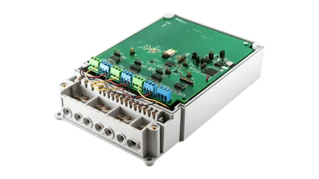
Energy Meter PCBAs We Manufacture
FLJ manufactures energy-meter boards and populated assemblies for residential billing, prepaid meters, DIN-rail submeters and commercial energy monitoring. Supply can cover the measurement PCBA, connected display and communication modules, or the electronics for a complete meter.
Single-Phase and Three-Phase Meter Boards
Single-phase boards measure the voltage and current for one supply phase; three-phase boards provide the corresponding measurement channels for the specified wiring system. Both can use different current-sensing arrangements. A direct-connected meter carries the measured line current through its input path, while an external-CT design accepts the transformer’s secondary signal through the specified input circuit. These choices change the sensors, terminals and channel configuration.
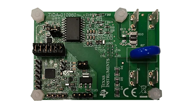
Meter configurations and supplied electronics
Scroll to view all columns.
| Meter configuration | Typical assembly content |
|---|---|
| Residential or prepaid meter | Metering and control board, display interface, and the input and switching components used by the design. |
| DIN-rail submeter | Compact measurement electronics with terminals and display or communication connections arranged for the enclosure. |
| Commercial three-phase monitor | Multiple measurement channels with the selected local interface, remote communication module and control functions. |
DIN-rail mounting describes the mechanical format. It can accommodate either single-phase or three-phase electronics, with direct or transformer inputs as the product requires.
Metering, Communication and Display Assemblies
The measurement section combines voltage and current inputs with a metrology IC, or an analog front end and a microcontroller that calculates the electrical quantities. Display, communication and control functions may share this board or occupy connected modules.
FLJ assembles these product-specific combinations: a metrology board linked to an LCD module, a measurement PCBA with a wired communication interface, or a controller carrying a wireless module and relay connections. Separate boards retain their defined interconnections and mounting positions, so the supplied electronics fit the intended meter architecture.
PCB Manufacturing and Metering Component Assembly
FLJ fabricates the circuit boards and assembles the sensing, metrology, power and interface components used in your meter. The build combines precise low-level measurement connections with the larger terminals, shunts and connectors that carry current or connect the finished unit.
PCB Constructions for Meter Electronics
We manufacture FR-4 and high-Tg FR-4 boards, imaging and etching the copper patterns, laminating multilayer constructions, drilling and plating interconnections, and routing the outline and specified slots. Copper geometry, sensing connections and insulation areas follow the circuit design; terminal holes and mounting features must also fit the mechanical assembly.
Typical meter PCB construction options
Scroll to view all columns.
| Construction | Layers | Board thickness | Nominal copper weight |
|---|---|---|---|
| Compact metering and control boards | 2–4 | 1.0–1.6 mm | 1–2 oz |
| Multichannel metering and interface boards | 4–6 | 1.6–2.0 mm | 1–3 oz |
These ranges describe construction options; the stack-up, copper distribution, holes and finished thickness are selected together. Finished conductor and hole-wall copper requirements follow the fabrication drawing. Phase count alone does not determine the board structure. Dense communication or control integration can require HDI, while the insulation system and working voltage determine the required clearances, slots and keep-outs.
Inner-layer pattern inspection takes place before multilayer lamination. Finished bare boards are checked for the required network continuity and isolation, with plated interconnections and critical mechanical features inspected against the fabrication requirements.
Precision-Component Sourcing and Assembly
FLJ provides component sourcing and approved alternative-part quotations for the metering BOM. We dynamically purchase specified components and compare available brand or model alternatives, including their technical differences, pricing and procurement lead times. Approved selections enter the production BOM before assembly.
For divider networks, CT burden resistors, shunts and references, tolerance and temperature drift affect the measurement chain. Filter values and dielectric type affect the input response; clock specifications and metrology-IC compatibility affect timing and calculation. Replacement assessment therefore includes electrical behavior, package and pinout, temperature grade, and any firmware or calibration changes. During assembly, these components retain their specified values, positions and channel assignments.
Discuss Parts and Assembly PricingSpecified BOM or approved component alternatives.
Shunts, Terminals and Mixed-Technology Connections
Paste printing, component placement and reflow assemble the analog front end and digital circuitry. Through-hole or selective soldering completes the applicable terminals, connectors and larger components, with the process suited to their thermal mass and the board construction. Shunt attachment follows the component drawing and the specified soldered or welded connection.
The load-current connection and the low-level shunt-sense connection perform different jobs. We preserve the specified sensing points, polarity and return paths when attaching the shunt and its leads. CT inputs likewise retain the required channel mapping and burden network. Terminal alignment and mechanical support are checked alongside the soldered connections so installation loads do not depend solely on a solder joint.
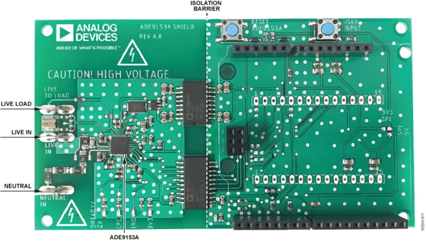
Calibration, Programming and Meter Testing
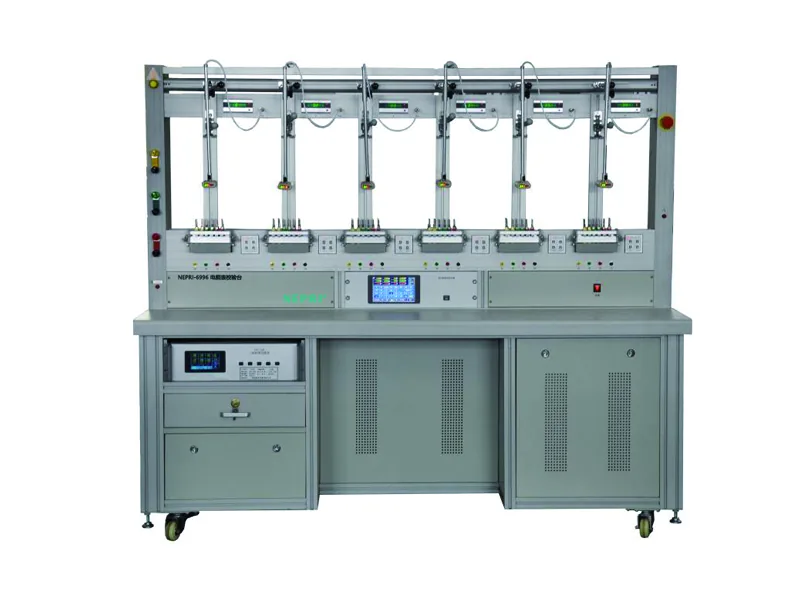
FLJ calibrates the assembled measurement channels, loads the meter program and configuration, and tests the functions included in your product. The production test plan connects each result to the board or meter being supplied.
Meter Calibration and Accuracy Verification
Component and reference variations affect measurement gain. CT phase delay can introduce further active-power error at low power factor, while small offsets become important at light loads. The metrology architecture and target performance determine which corrections are required.
We apply the specified voltage, current and phase conditions and compare the meter response with a suitable reference meter or accurate source. Readout uses the configured calibration pulses or measurement registers. The pulse constant, channel and measured quantity must correspond to the test setup. After adjustment, accuracy verification covers the specified operating points. Records associate the input conditions, channel, measured error, reference identification and calibration data with the individual unit.
Firmware, Meter Parameters and Data Readback
Our IC programming service loads the released firmware together with the configuration required by the meter: sensor ratio, channel mapping, pulse constant, communication address, or time and tariff settings where used. Unit-dependent calibration coefficients remain associated with the correct board and channels.
Programming verification uses the device-supported readback or verification method. We check the required stored data and operating configuration; measured accuracy is verified separately through the metrology test. This keeps a successfully written coefficient from being mistaken for a verified measurement result.
Display, Communication and Switching Tests
Our board-level functional testing exercises the fitted interfaces and controls. Typical checks are selected around the functions your meter actually contains:
Meter functions and production checks
Scroll to view all columns.
| Function | Test input or action | Observed response |
|---|---|---|
| Display and user input | Select data pages, operate keys or apply a prepaid test input. | Required segments, values, status and input response. |
| Communication | Address the configured interface and issue a defined transaction. | Correct response and data fields. |
| Clock and tariff functions | Apply the specified time or tariff test condition. | Expected register or displayed state. |
| Load switching | Command the fitted relay under the specified test conditions. | Required contact state and load response. |
Specified insulation or withstand tests identify the test nodes, method, level and duration. EMC and environmental verification follow the product qualification plan, with their scope and records included in the ordered supply.
Complete Energy Meter OEM Assembly
FLJ integrates the assembled metrology electronics, display and communication modules into complete DIN-rail or panel-mounted meters. The work follows your electronic design, firmware and mechanical drawings, bringing the internal connections, enclosure and product identification into the same manufacturing order.
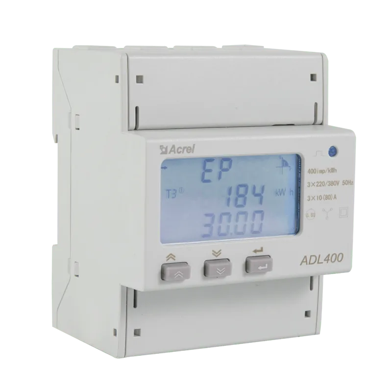
Our box build assembly includes mounting the PCB, aligning terminals with the housing openings, fitting the LCD and buttons, and routing internal wires between the metrology, display and communication sections. We check connector orientation and wire polarity, secure the specified supports and fasteners, and provide strain relief where the design requires it. Display windows and terminal access must remain usable after the enclosure is closed.
The integrated unit carries the configuration for its input variant and installed modules. Final checks cover the assembled connections and the functions defined for that meter, including its display, communications or switching outputs. Unit identification links the supplied hardware and program configuration with the ordered manufacturing and measurement records.
We fit terminal covers and the specified accessories, apply your product labels and serial identification, and package the completed meters for shipment. Input-variant markings and identification correspond to the installed hardware and configuration.
Energy Meter PCB Assembly FAQs
Can FLJ supply bare meter PCBs, assembled boards and complete meters?
Yes. FLJ supplies fabricated PCBs, populated metering and communication boards, and complete meter assemblies. The quotation identifies the included components, programming, tests, display, terminals, wiring and enclosure so the delivered hardware matches your order.
Do you assemble both single-phase and three-phase meter boards?
Yes. We manufacture both configurations, including direct-connected and current-transformer input designs. The input circuit, channel mapping, terminal arrangement and calibration plan follow the selected design; a three-phase board does not automatically require CT inputs.
Can you source precision components and propose alternatives?
Yes. Our sourcing service includes component procurement, alternative-brand recommendations and quotations. Comparisons cover the electrical specification, tolerance, temperature behavior, package and program compatibility. Approved substitutions enter the build BOM, with any required calibration changes addressed.
Can firmware and calibration data be programmed during production?
Yes. We load the specified firmware and supported unit data, such as serial numbers, channel settings and calibration coefficients. Programming verification uses the device-supported method; measurement checks separately verify the calibrated meter’s response.
What is included in energy-meter calibration and accuracy testing?
The plan defines the reference, input voltage and current, power factor, channels and acceptance limits. It covers applicable adjustments and verification points for the meter architecture, with results associated with the unit and its configuration.
How are communication and insulation requirements verified?
Communication checks exercise the specified interface and expected transactions. Insulation testing follows the designated circuit boundaries, test method, voltage and duration. These requirements are defined for the product rather than inferred from its PCB construction.
What files and specifications are needed for an energy-meter quotation?
Provide fabrication and drill data, stack-up, BOM, assembly drawings, quantities and delivery requirements. Include programming and test requirements for PCBA supply, plus enclosure and wiring drawings for complete meters. Our contact form prepares your enquiry as an email draft.