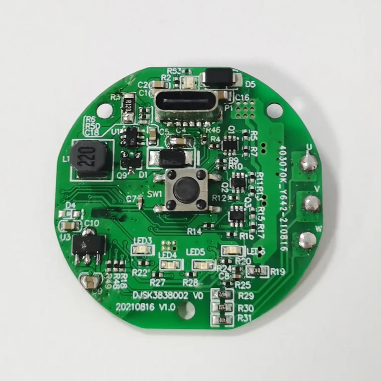
Design and manufacturing capabilities
| Design layer-count capability | 1–32 layers |
|---|---|
| Minimum line width and spacing | 3mil |
| Minimum laser-drilled hole | 4mil |
| Minimum mechanically drilled hole | 8mil |
| Copper foil thickness | 18–175 µm (standard values: 18 µm, 35 µm and 70 µm) |
| Peel strength | 1.25N/mm |
| Minimum punched-hole diameter | Single-sided: 0.9 mm / 35 mil |
| Minimum hole diameter | 0.25mm/10mil |
| Hole-diameter tolerance | For diameter ≤0.8 mm: ±0.05 mm |
| Hole-diameter tolerance | ±0.05mm |
| Plated-hole wall copper thickness | Double-sided / multilayer: ≥0.8 mil |
| Hole resistance | Double-sided / multilayer: ≤300 µΩ |
| Minimum line width | 0.127mm/5mil |
| Minimum spacing | 0.127mm/5mil |
| Legend-colour options | Black, white, red, green and other colours |
| Surface-finish options | Leaded or lead-free HASL, ENIG, silver and OSP |
| Service | OEM services |
| Quality and compliance references | ISO 9001 / RoHS / UL |
RF technology and identification
RF stands for radio frequency. One common application is radio-frequency identification, or RFID, used in contactless identification chips, proximity cards, electronic tags and electronic barcodes.
A scanner emits radio-frequency energy at a specified frequency. The receiving circuit uses that energy to return its identification code, which the scanner then reads.
Passive receiving devices do not need a battery, physical contacts or card-swiping. Contactless operation helps them work where dirt would interfere with exposed contacts. Chip identifiers support item identification, security-related applications and long service life.
Typical RFID applications include animal identification, vehicle anti-theft systems, access control, parking control, production-line automation and materials management.
RFID tags and readers
RFID tags are divided into active and passive types. An electronic tag may also be called an RF tag, transponder or data carrier. A reader may be described as a reading device, scanner or communicator, depending on whether the tag supports wireless rewriting.
The tag and reader exchange radio-frequency energy and data through non-contact coupling elements. The coupling channel enables energy transfer and data exchange according to the required timing relationship.
Two radio-frequency coupling methods
- Inductive coupling: the transformer model uses a high-frequency alternating magnetic field across space. Its operating principle is electromagnetic induction.
- Electromagnetic backscatter coupling: the radar model uses an emitted electromagnetic wave that is reflected by the target and returns information about that target. It follows the principles of electromagnetic-wave propagation.
Inductive-coupling systems
Inductive coupling is generally used for short-range RFID at low and high frequencies. Typical operating frequencies include 125 kHz, 225 kHz and 13.56 MHz. The identification distance is less than 1 m, with a typical range of 10–20 cm.
Backscatter systems
Electromagnetic backscatter coupling is generally used for longer-range RFID at UHF and microwave frequencies. Typical frequencies include 433 MHz, 915 MHz, 2.45 GHz and 5.8 GHz. Identification distances exceed 1 m, with a typical range of 3–10 m.
Consumer-electronics RF design support
FLJ PCB provides consumer-electronics RF PCB design and one-stop PCBA assembly support, drawing on experience across circuit-board design and manufacturing.