
In order to meet more demands from different electronics engineers, tons of design software and tools appear for them to choose and use, some are even for free. However, when you submit your design files to manufacturer and assemble PCBs, you might be told it’s not available to use. Here, I’ll share you with valid PCB files for PCB manufacturing and assembling.
1. Design Files for PCB Manufacturing
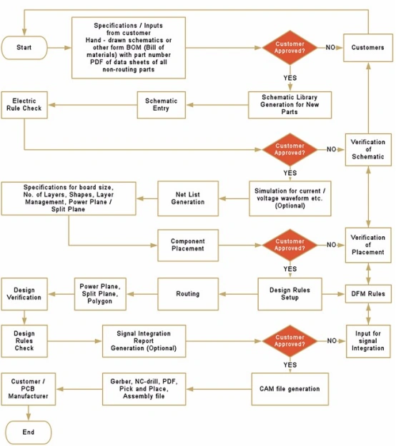
If you want to produce your PCBs, PCB design files are necessary, but what form of files should we export? In general, Gerber files with RS-274-X format are widely used in PCB manufacturing, which can be opened by CAM350 software tool.
Export each required copper, solder-mask, silkscreen and outline layer with an unambiguous layer map. Supply the NC drill data separately, including plated and non-plated hole identification, units and origin. Add a fabrication drawing with stackup, finished thickness, copper requirements, material, finish, tolerances and controlled-impedance notes where applicable.
2. The Files for PCB Assembly
1) Centroid File/Pick&Place File
Centroid file/Pick&Place File contains the information about where each component should be placed on the board. There’re X and Y Coordinate of each part, as well as rotation, layer, reference designator, and the value/package.
2) Bill of Materials (BOM)
The BOM (Bill Of Materials) is a list of all the parts which will be populated on the board. The information in the BOM must be enough to define each component, the information from BOM is very critical, must be complete and right without any mistakes. A complete BOM will reduce a lot of trouble in components.
For each BOM line, include the reference designators, quantity, manufacturer name and manufacturer part number, plus value and package where useful. Mark DNP items and approved alternates explicitly. A distributor link or part value alone may not uniquely identify the component.
3) Assembly Drawings
An assembly drawing helps when there’s trouble to find the position of all components in BOM, and it also helps for engineer and IQC to check and find the issues by comparing it with PCBs which are made, especially the orientation of some components.
4) Special Requirements
If there’re any special requirements which are difficult to describe, you can also show it in pictures or videos. It will help a lot for PCB Assembly.
5) Test and IC Programming
If you want your manufacturer to test and program IC in their factory, It’s required for all files of programming, the method of programming and test, and the test and programming tool might be used.
Before production release, confirm that fabrication data, BOM, placement file, drawings, firmware and test instructions all carry the same revision. Resolve origin, rotation and polarity conventions with the assembler. If the project is still being priced, use the PCBA quotation-file checklist; this page covers the release package needed to build and test the agreed revision.