Industrial motherboard layout features
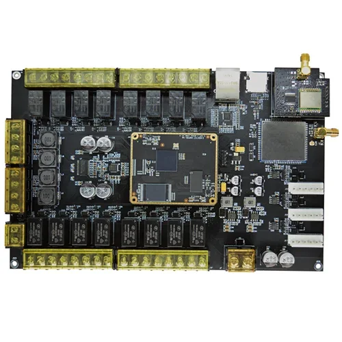
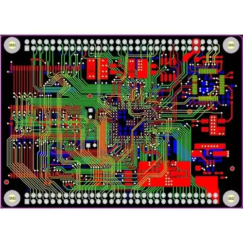
- The layout is highly integrated and dense. The holes and filter-capacitor geometry around BGA areas are adapted to the available layout space.
- For 25G high-speed signals, the layout uses a 10-degree routing angle. The referenced Intel-recommended approach is used to address the glass-weave effect.
PCB design parameters
| Layer count | 14 layers |
|---|---|
| PCB construction | Through-hole board |
| Laminate / board specification | Htg70 |
| PCB thickness | 2.0MM |
| Board dimensions | 458*208MM |
| Surface-finish options | Immersion gold |
| Copper weight | 1OZ |
| Minimum line width | 4MIL |
| Minimum spacing | 4MIL |
| Minimum hole diameter | 8MIL |
| Impedance control | +/-5% |
Industrial-control board functions
Industrial-control circuit boards control the operation of electrical equipment.
- Reserved I/O for equipment: a dedicated or general-purpose board provides the underlying circuitry and input/output ports. These connect to motors, solenoid valves and sensors to implement the intended functions.
- Boards for a defined task: a dedicated board is developed for a particular function. A temperature-control board, for example, can connect a thermocouple to the input and a heating contactor or solid-state relay to the output. Other applications include current control and motion control.
- Programmable general-purpose control: many universal control boards support user programming and further development. A PLC is a familiar example. The user writes, compiles and loads a program to work with digital inputs, analog inputs, high-speed counters, digital outputs and analog outputs. Some boards also provide communications functions.